

To create architectural drawings, you measure the existing conditions, build an accurate model or base plan, and then produce a set of scaled drawings: site plan, floor plans, elevations, sections and details, each with dimensions, notes and a title block. For a home addition or remodel, a typical architectural drawing package has five to ten sheets and shows both what exists today and what will be built.
The work is easier than it sounds if you use software that creates the plans, sections and elevations from one model. With a program such as Plan7Architect Pro, you draw the building once and take every drawing from it, so the floor plan and the elevation can never disagree.
Below I explain what belongs in an architectural drawing package, which scales and conventions are used, and how to create the drawings step by step, using a home addition as the example.

What an Architectural Drawing Package Includes
Architectural drawings describe a building from above, from the side and in cut. For a residential addition, the package usually contains these sheets:
| Sheet | Content | Common scale |
|---|---|---|
| Cover sheet | Project name, address, sheet index, general notes | None |
| Site plan | Lot lines, setbacks, existing house, addition, driveway | 1 inch to 20 feet or 1:200 |
| Existing floor plan | The house as it is today, walls to be removed marked | Quarter inch to the foot or 1:50 |
| Proposed floor plan | New walls, doors, windows, room names, dimensions | Quarter inch to the foot or 1:50 |
| Elevations | All affected facades with heights and materials | Quarter inch to the foot or 1:50 or 1:100 |
| Building sections | Vertical cuts with floor, ceiling and roof heights | Quarter inch to the foot or 1:50 |
| Roof plan | Roof slopes and the connection to the existing roof | Eighth inch to the foot or 1:100 |
| Details | Wall build-up, foundation, roof edge, connections | 1 inch to the foot or 1:10 to 1:20 |
Depending on the project and the local rules, structural, electrical and plumbing drawings are added. Our article on the types of construction drawings describes each kind in more detail.
Conventions Every Architectural Drawing Follows
Scale
Every drawing is drawn to a stated scale, and the scale is printed on the sheet. Builders take dimensions from the numbers, but a correct scale lets them check things quickly with a scale ruler.
Try the scales from the table yourself: enter a real dimension to see its size on paper, or check which sheet your plan fits at a given scale.
Line Weights
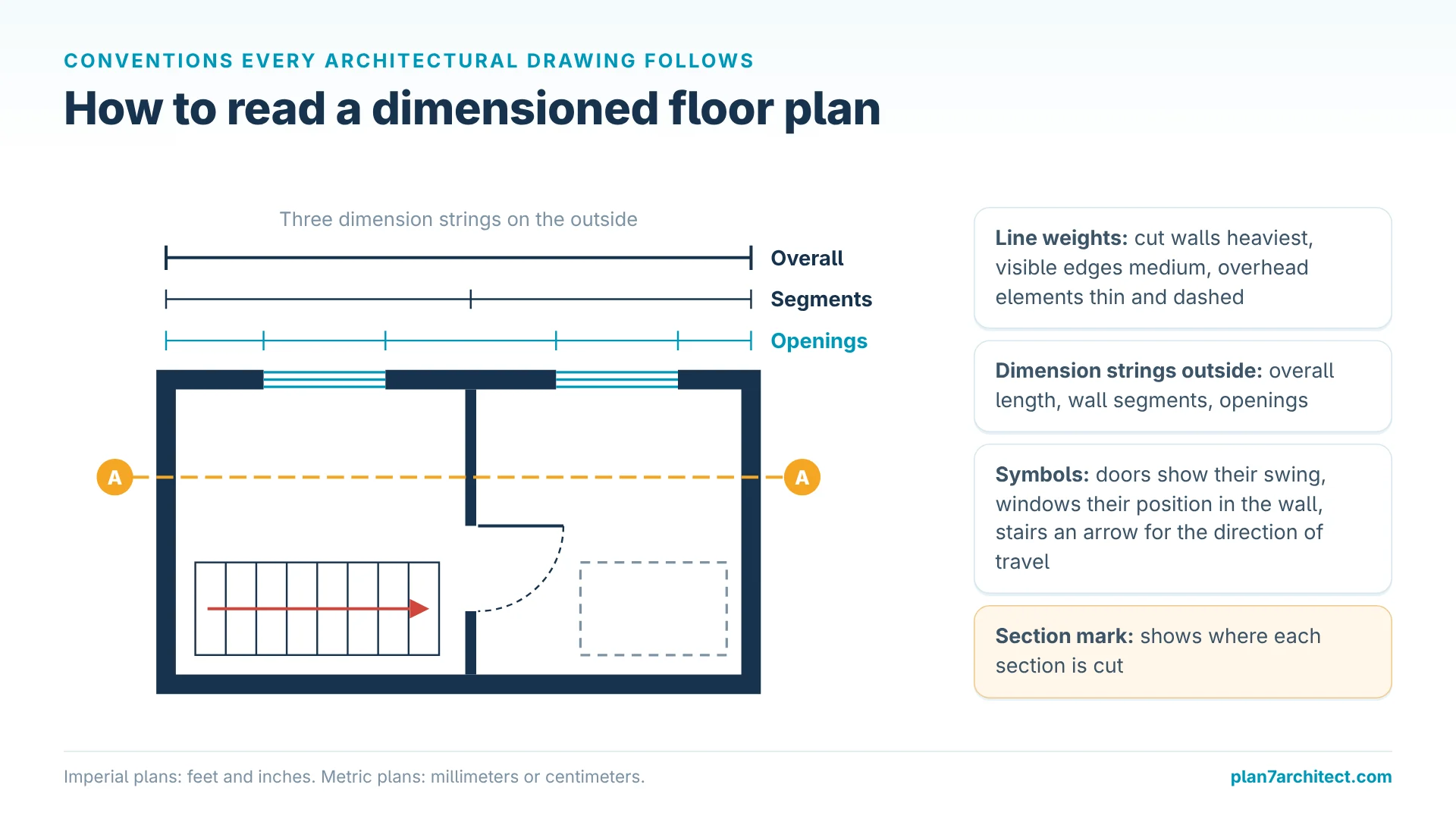
Cut walls are drawn with the heaviest lines, visible edges with medium lines, and hidden or overhead elements with thin dashed lines. This hierarchy makes a plan readable at a glance.
Dimensions
Floor plans usually carry three dimension strings on the outside: overall length, wall segments and openings. Interior dimensions locate walls and rooms. Imperial plans are dimensioned in feet and inches, metric plans in millimeters or centimeters.
Symbols and Notes
Doors show their swing, windows their position in the wall, stairs an arrow for the direction of travel. Section marks in the floor plan show where each section is cut.
Title Block
Each sheet has a title block with the project, address, sheet name and number, scale, date and revision. Standard sheet sizes are explained in our article on construction drawing sheet sizes.
How to Create Architectural Drawings Step by Step
This is the process I use for a residential addition.
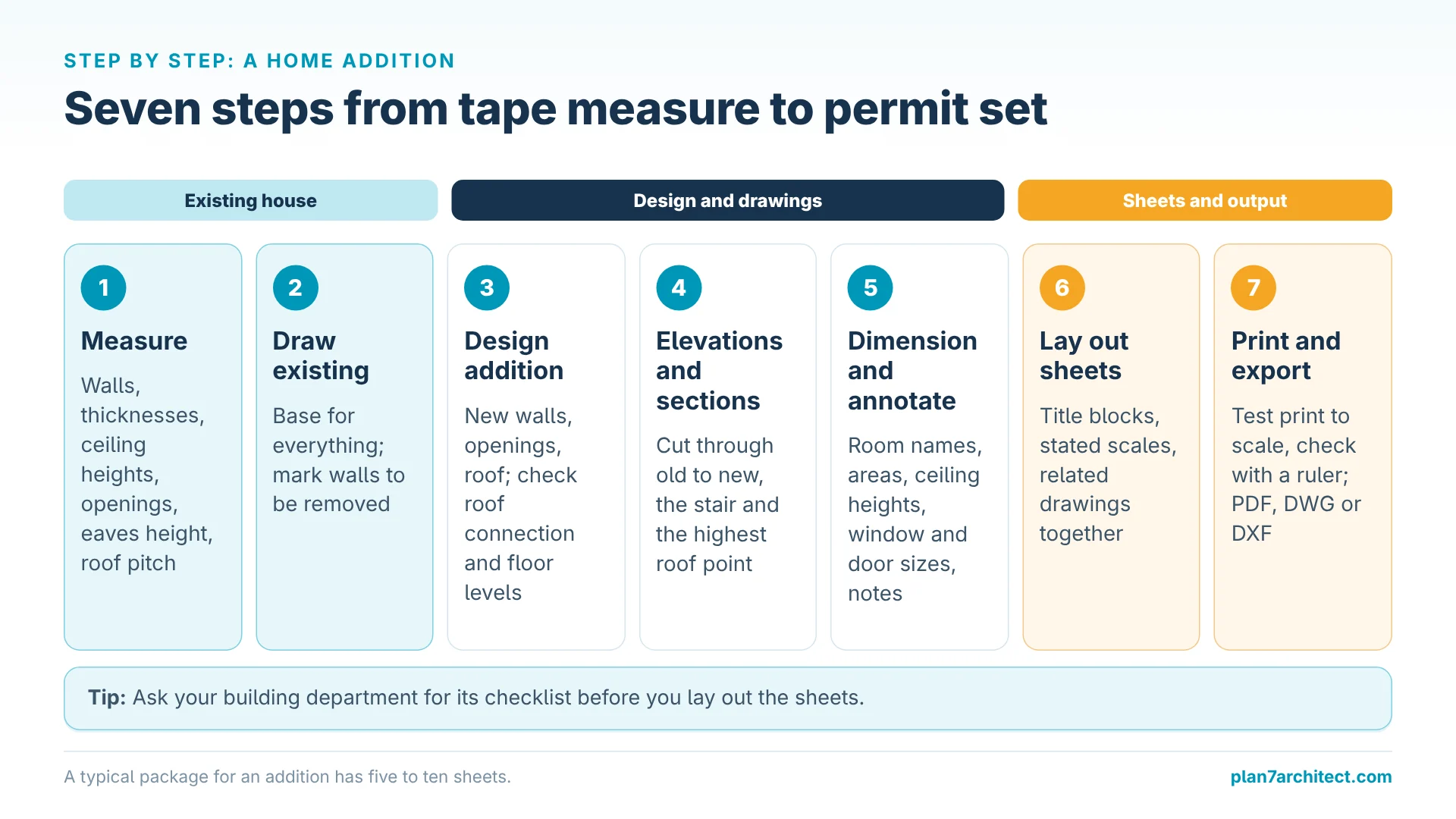
1. Measure the Existing House
Measure every room that the addition touches: wall lengths, wall thicknesses at the openings, ceiling heights, window and door sizes and their heights above the floor. Measure the outside too, including the eaves height and the roof pitch. If you have old plans, check them against reality; they are often inaccurate.
2. Draw the Existing Conditions
Build the existing house in your software first. This becomes the existing floor plan and the base for everything else. Mark the walls that will be removed.
3. Design the Addition
Add the new walls, openings and the roof. Check how the new roof meets the existing one and whether the floor levels line up. Our guide on designing a home addition that works covers the design decisions.
4. Generate Elevations and Sections
Place section lines through the critical areas: the connection between old and new, the stair, the highest roof point. Generate the elevations of all sides that change.
5. Dimension and Annotate
Add dimension strings, room names, areas, ceiling heights, window and door sizes and short material notes.
6. Lay Out the Sheets
Arrange the drawings on sheets with title blocks, at the scales listed above. Keep related drawings together: plans on one sheet, elevations on the next.
7. Print, Export and Review
Print a test sheet to scale and check a few dimensions with a ruler. Save the set as PDF and export DWG or DXF for the engineer and the contractor.
Creating the Drawings in Plan7Architect
In Plan7Architect, architectural drawings come from one building model. Walls, floors, ceilings, roofs and stairs are real objects, so the floor plan, sections, elevations and 3D view are always synchronized.

For an addition, this means you draw the existing house once, add the new part, and the program produces the plans from it. Dimensions are created automatically and can be adjusted. Section lines placed in the floor plan create sections with correct floor and roof heights. Layer management keeps existing and new elements apart, and plan variants let you compare two versions of the addition before you choose one.
The plan assembly places floor plans, sections and elevations on sheets with title blocks. You print to scale or save as PDF, and export DWG or DXF. If you start from an old drawing, you can import it as an image or a DWG and trace over it. Our tutorial on drawing elevations and section views shows these steps in the program.
DIY Architectural Drawings: What You Can Do Yourself
Homeowners can prepare most of an architectural drawing package themselves, especially for additions, garages, decks and remodels. In many areas, owners may submit their own drawings for smaller projects. For structural elements such as beams, new foundations or removed load-bearing walls, an engineer usually has to provide calculations or details, and some jurisdictions require stamped drawings for any addition. Check your local requirements before you start.
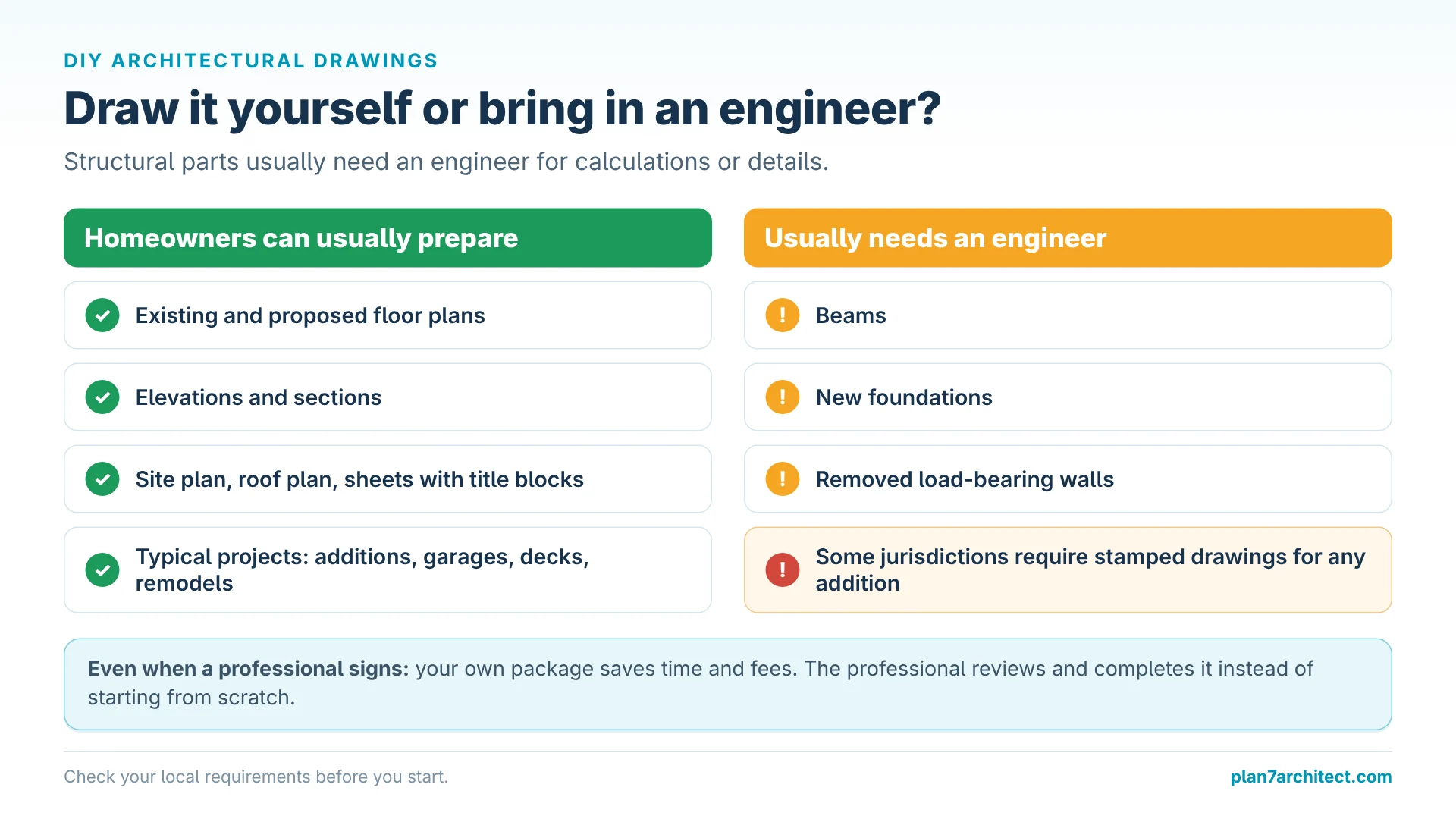
Even when a professional has to sign the drawings, your own package saves time and fees. The professional reviews and completes a finished set instead of drawing everything from scratch, and in my experience the result is closer to what you wanted.
Common Mistakes in Architectural Drawings
Missing Existing Conditions
Drawing only the new part leaves the reviewer guessing how it connects. Always show the existing house next to the addition.
Dimensions That Do Not Add Up
If the wall segments do not sum to the overall length, the contractor will call you. Software with automatic dimensions avoids this.
Sections in the Wrong Place
A section through an ordinary room shows little. Cut through the stair, the roof connection and the tallest point.
Create Your Architectural Drawings with Plan7Architect
With Plan7Architect Pro you can create professional architectural drawings yourself: existing and proposed floor plans with automatic dimensions, walls, doors, windows, stairs and roofs, sections, elevations and plan sheets with title blocks, all from one model with a 3D view. You work in feet and inches or metric units, print to scale and export as PDF, DWG or DXF for your engineer, contractor and building department. It costs Original price was: $259.99.$99.99Current price is: $99.99. once, without a subscription. Every purchase includes a 14-day right of withdrawal, so you can simply cancel your purchase by email if the software is not right for you.

Plan your project with Plan7Architect

Plan7Architect Pro 5 for Original price was: $259.99.$99.99Current price is: $99.99.
You don’t need any prior experience because the software has been specifically designed for beginners. The planning process is carried out in 5 simple steps:
1. Draw Walls

2. Windows & Doors

3. Floors & Roof

4. Textures & 3D Objects

5. Plan for the Building Permit

6. Export the Floor Plan as a 3D Model for Twinmotion

- – Compliant with international construction standards
- – Usable on 3 PCs simultaneously
- – Option for consultation with an architect
- – Comprehensive user manual
- – Regular updates
- – Video tutorials
- – Millions of 3D objects available
Why 85,000+ Home Planners Choose Plan7Architect
Why choose Plan7Architect over other home design tools?
Watch how a complete house is planned from start to finish – in under 25 minutes
Detailed House Planning (25 Min)

Small Home Planning Demo (12 Min)

Short House Planning Demo (6 Min)

Your Plan + AI
Plan your house in Plan7Architect and take it further with today’s AI tools. Your design stays exactly as you planned it.


Plan7ArchitectAI
Photorealistic AI Renderings
Turn any 3D view of your Plan7Architect project into a photorealistic image in seconds.
How to render your design with AI →Free prompt generator with 11 examples →
AI Videos of Your HouseNew
A short film like real drone footage, made from your Plan7Architect 3D views.
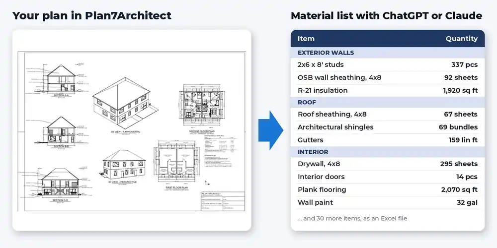
Material List & Cost Estimate
Export your plan as DXF and let ChatGPT or Claude create quantities and a cost estimate.

Digitize Floor Plans with AI
Paper, PDF or photo to an exact DXF file you can trace in Plan7Architect.
The 3 Plan7Architects

Suitable for small hobby projects
No garden planning and only limited floor plan creation with few wall types
★★★★★

For medium-sized projects
Unrestricted floor plan creation & garden planning
No export options for your architect and no plans for building permit applications
★★★★★
For projects of any size
Import & export for working with an architect
Create plans for real building permit applications
Much larger range of features than the other two versions
★★★★★
Verified Customer Reviews
More on this topic: Construction Drawings, Elevations & Permit Plans – all articles
You might also like: