Working drawings and construction drawings are often confused, but they are not exactly the same. Construction drawings describe the overall design and intent of a building project, while working drawings provide the technical details needed for actual execution on site. In simple terms: construction drawings show what the building should look like, and working drawings explain how it should be built.
Quick overview:
-
Working Drawings → Technical, detailed instructions for builders and trades
-
Construction Drawings → Broader design documents used for approvals, clients, and general planning
What Are Working Drawings?
Definition and Purpose
Working drawings are the documents that contractors and trades rely on when carrying out the construction. They contain precise, technical information and leave no room for interpretation. Without them, on-site workers would have to guess dimensions, materials, or installation methods.
Key Elements Included in Working Drawings
Typical components of working drawings include:
-
Exact dimensions (available in both metric and imperial units)
-
Materials and specifications
-
Structural reinforcements
-
Electrical layouts
-
Plumbing systems
-
HVAC installations
-
Fixing details for doors, windows, and furniture
Who Uses Them?
Working drawings are mainly used by:
-
Builders and contractors
-
Electricians, plumbers, and other trades
-
Engineers supervising the execution
-
Site managers responsible for coordination
What Are Construction Drawings?
Definition and Purpose
Construction drawings form the larger documentation set that communicates the design intent. They serve as the “language” between architects, clients, and authorities. Construction drawings are usually less detailed than working drawings, but they give a complete overview of the building project.
Key Elements Included in Construction Drawings
Common parts of construction drawings are:
-
Floor plans and elevations
-
Cross sections
-
Roof layouts
-
Site plans with boundaries and orientation
-
Window and door schedules
-
Finishing schedules
Who Uses Them?
Construction drawings are primarily used by:
-
Architects and designers
-
Clients who want to understand the project
-
Local authorities for building approvals and permits
-
Quantity surveyors for tendering and cost estimation
Side-by-Side Comparison
| Aspect | Working Drawings | Construction Drawings |
|---|---|---|
| Purpose | Guide for on-site execution | Communicate design and intent |
| Level of Detail | Very detailed, technical | Broader, less technical |
| Users | Builders, trades, engineers | Architects, clients, permit authorities |
| Content | Dimensions, materials, technical specs | Layouts, plans, elevations, general details |
| Stage | Used during actual construction | Used during design, planning, and approvals |
Why the Terms Are Often Confused
The terms are sometimes used interchangeably, especially in regions where working drawings are simply considered part of the construction drawing set. However, the distinction is clear: construction drawings cover the big picture, while working drawings focus on the fine details needed for execution.
Practical Example
Imagine you are planning a residential home:
-
The construction drawings will show the floor plan, the site plan, the elevations, and how the house fits on the property.
-
The working drawings will specify wall thicknesses, reinforcement for foundations, pipe layouts, wiring diagrams, and the installation details for fixtures.
Tips for Readers (When Reviewing or Creating Drawings)
-
Check that you receive both sets of drawings: design-level and detailed execution-level.
-
Ensure the measurements are in the units common to your region. If you are working internationally, make sure the software allows you to switch between metric and imperial units easily.
-
If you notice that only the general plans are provided but no technical details, ask for the missing working drawings before construction begins.
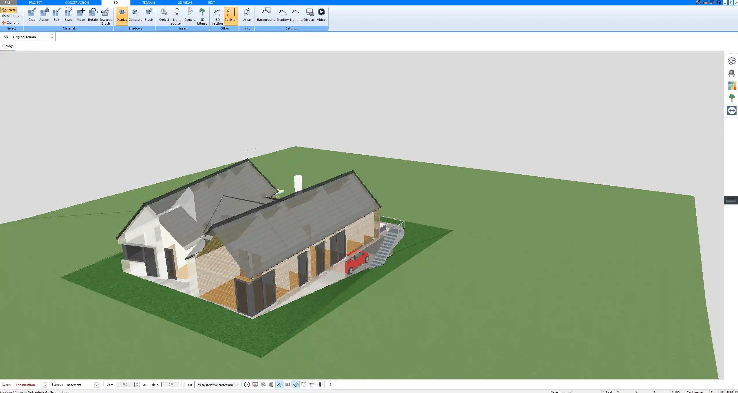
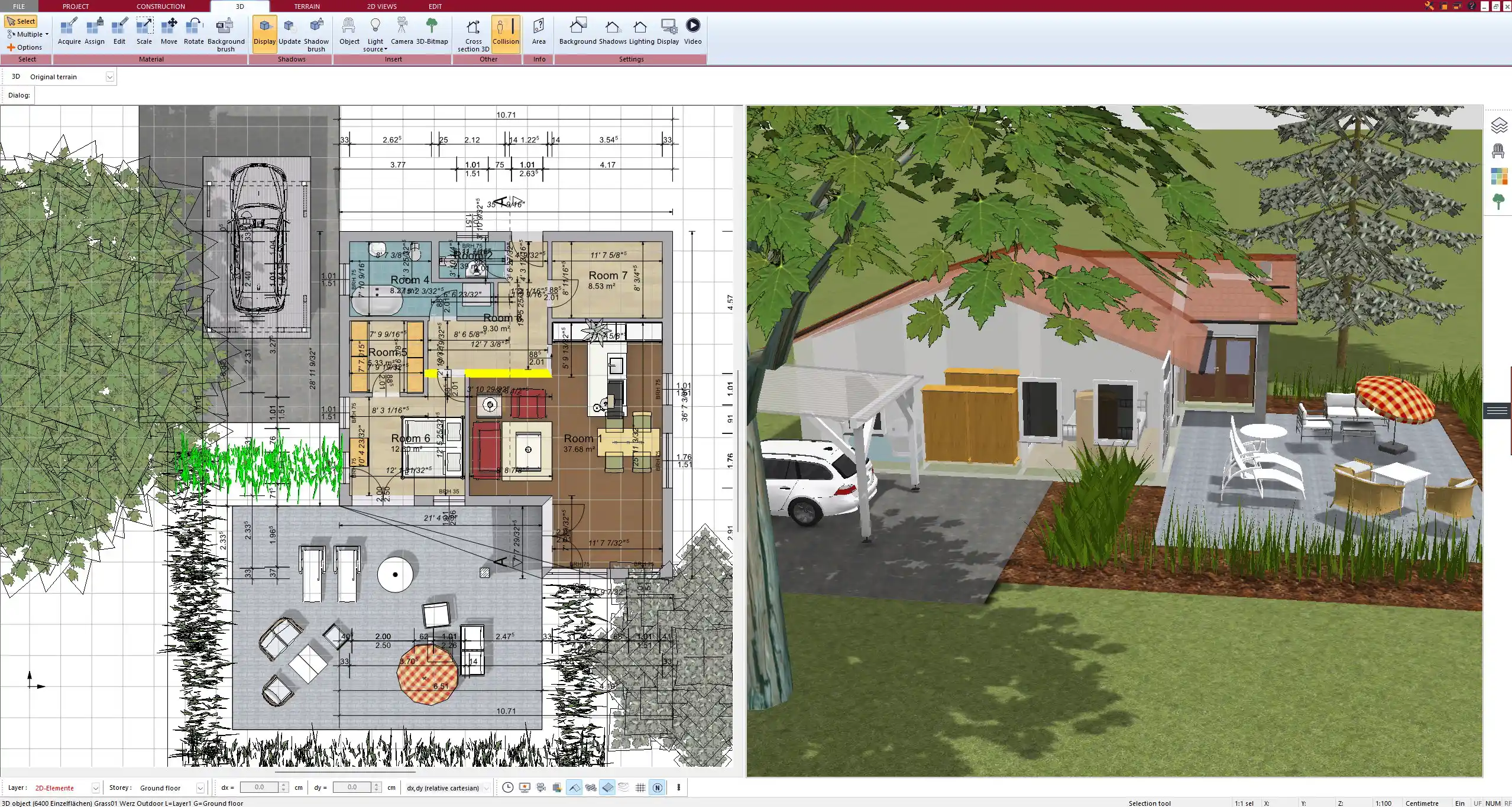
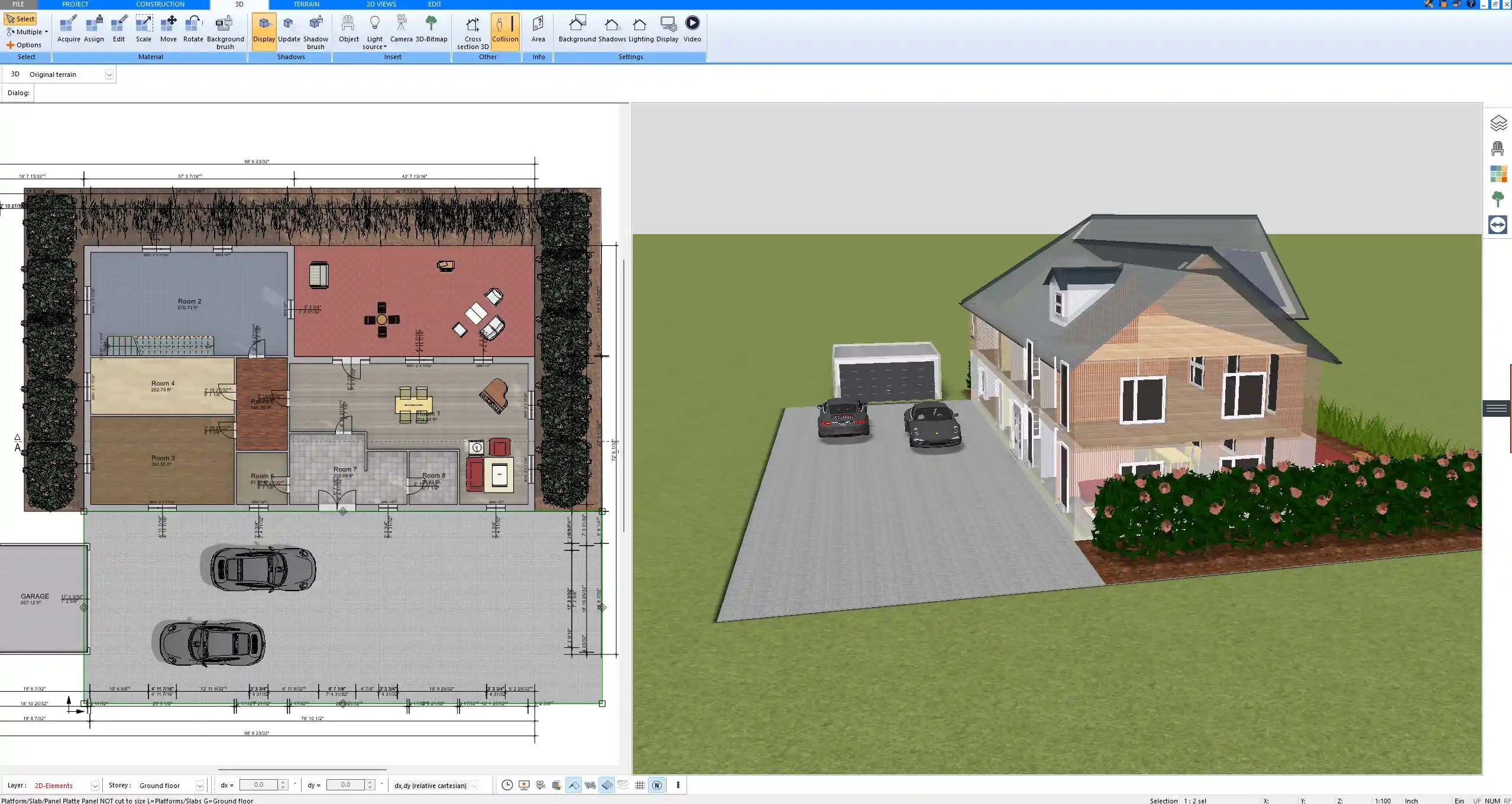
Create Professional Floor Plans with Plan7Architect
With Plan7Architect you can design both construction drawings and detailed working drawings for your projects. You can plan floor layouts, create elevations, add dimensions, and specify technical details for trades and contractors. The software allows you to work with both European and American units, so you can adapt your plans for any region. If you want to prepare professional drawings yourself, Plan7Architect gives you the right tools. You also benefit from a 14-day cancellation policy, meaning you can cancel your purchase easily by email if you are not satisfied. This flexibility replaces the need for a trial version and lets you test the software risk-free. Would you like me to also prepare six image caption texts for this article that clearly show Plan7Architect in action, so readers can instantly connect the visuals with the explanations?
Plan your project with Plan7Architect

Plan7Architect Pro 5 for $109.99
You don’t need any prior experience because the software has been specifically designed for beginners. The planning process is carried out in 5 simple steps:
1. Draw Walls

2. Windows & Doors

3. Floors & Roof

4. Textures & 3D Objects

5. Plan for the Building Permit

6. Export the Floor Plan as a 3D Model for Twinmotion

- – Compliant with international construction standards
- – Usable on 3 PCs simultaneously
- – Option for consultation with an architect
- – Comprehensive user manual
- – Regular updates
- – Video tutorials
- – Millions of 3D objects available
Why Thousands of Builders Prefer Plan7Architect
Why choose Plan7Architect over other home design tools?