Construction drawings in architecture are the official, scaled documents that guide every step of the building process. They translate an architect’s design into precise instructions for contractors, engineers, and builders. These drawings show dimensions, materials, and technical details in a way that leaves no room for misunderstanding. They are legally binding and form part of the construction contract, making them one of the most essential tools in any building project.
Key Purposes of Construction Drawings
Construction drawings serve several important functions:
-
Provide a visual and technical representation of the design
-
Communicate details to contractors, builders, and engineers
-
Ensure the project complies with local building regulations
-
Serve as the foundation for accurate cost estimation
-
Act as a schedule reference throughout the construction process
When you look at a complete set of drawings, you are not just seeing lines and measurements; you are holding the roadmap to the finished building.
Types of Construction Drawings
Floor Plans
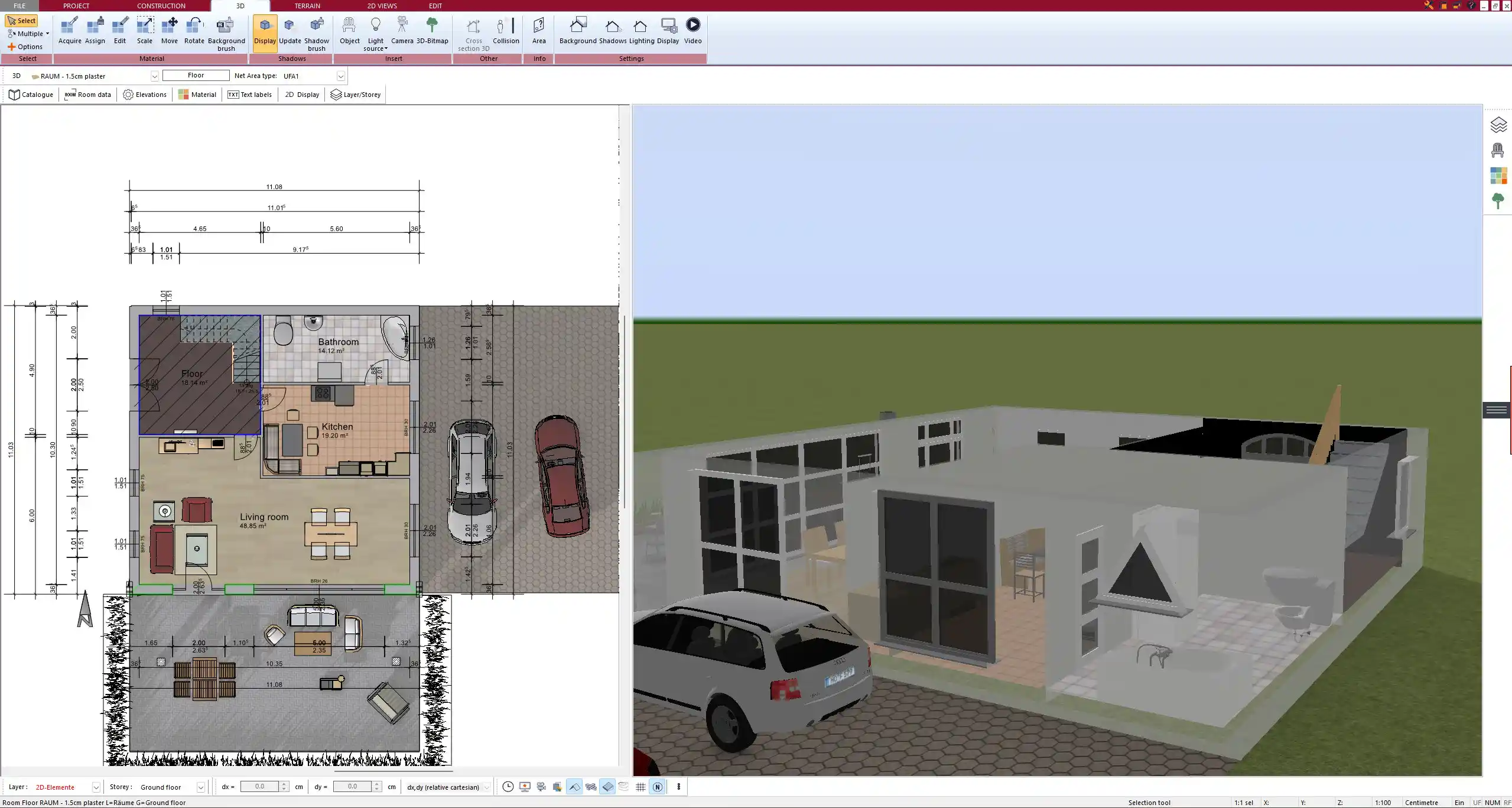
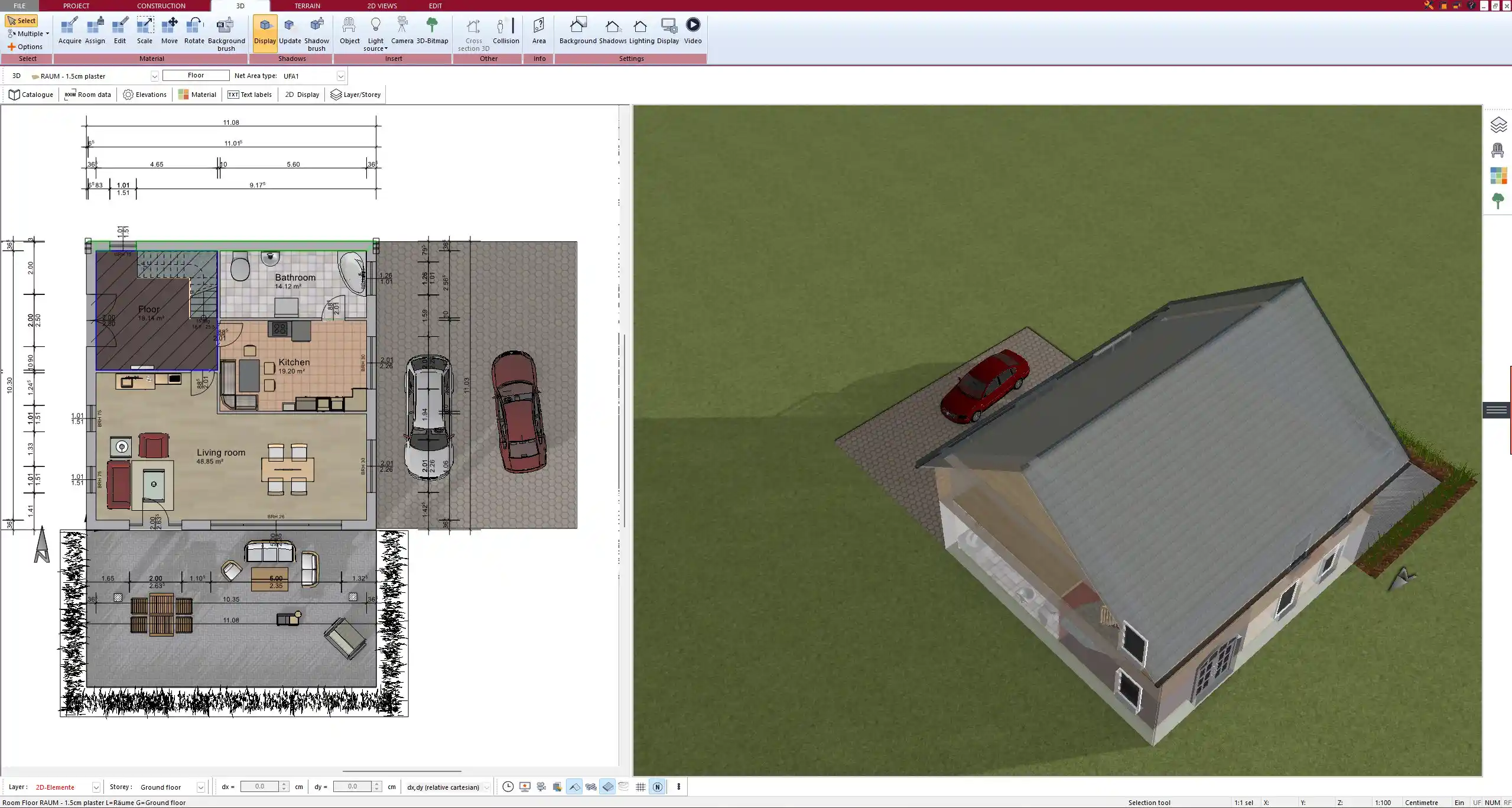
Floor plans show the arrangement of rooms, doors, walls, and windows in a building. They include dimensions, wall thicknesses, circulation routes, and placement of fixtures. A typical floor plan will make it easy to understand how people will move through a building and how spaces relate to one another.
Elevations
Elevation drawings present the vertical faces of the building, both exterior and interior. They highlight wall finishes, materials, window designs, and overall building height. Elevations are crucial when choosing materials and ensuring that the aesthetic vision is properly communicated to the builder.
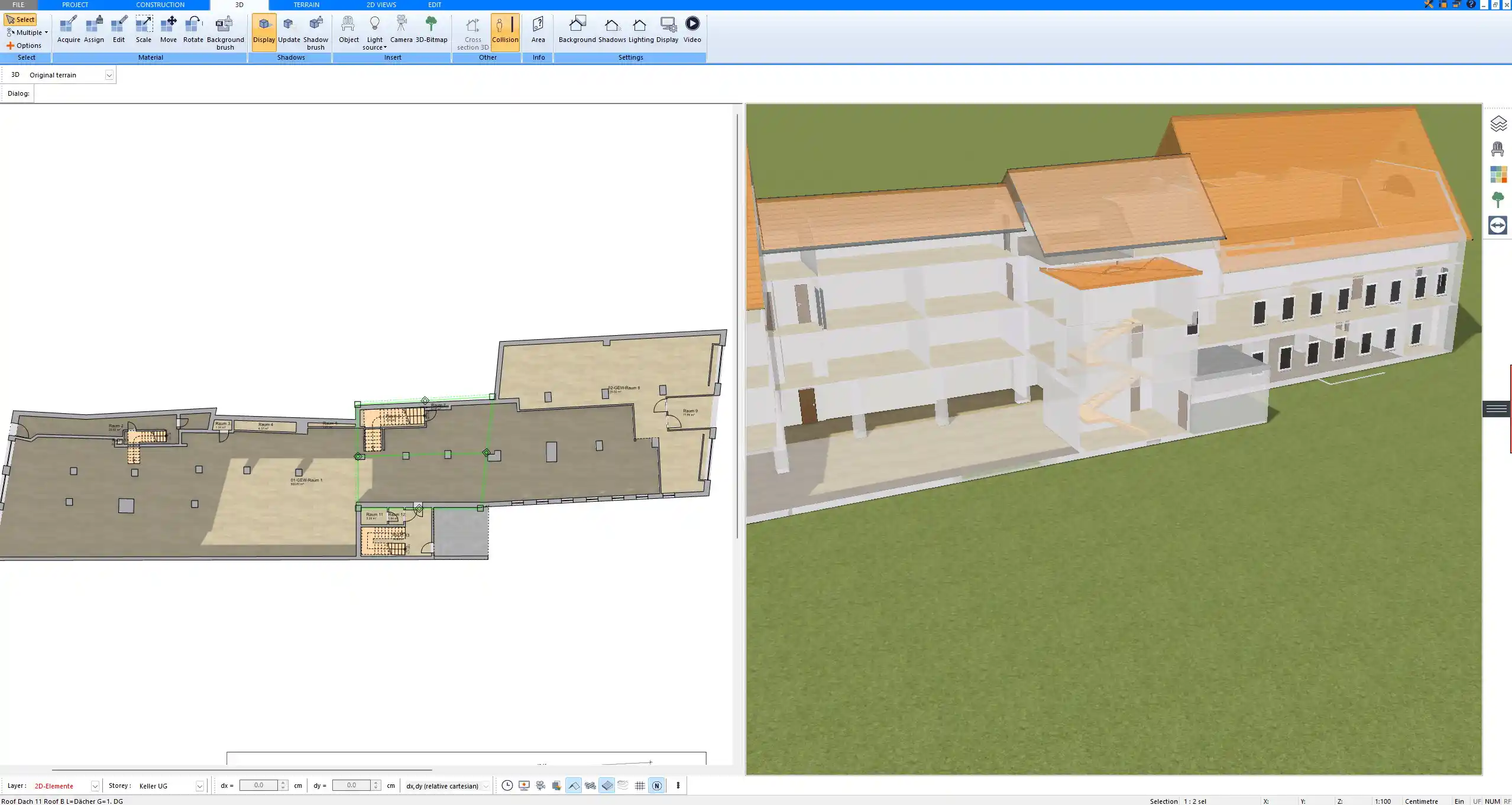
Sections
Sections cut through the building to reveal its structure. These drawings make it possible to see how floors, ceilings, walls, and roofs connect. They are particularly useful for understanding construction layers, insulation, and changes in level.
Detail Drawings
Details provide enlarged views of specific construction elements. They might show how a window frame is installed, how a staircase is constructed, or how roof components are joined. Without these details, contractors might interpret important aspects differently, which could lead to costly mistakes.
Site Plans
A site plan shows how the building sits on the property. It includes boundaries, landscaping, driveways, parking spaces, and surrounding structures. Orientation is also a vital part of site plans, helping with decisions related to sunlight, shading, and ventilation.
Structural, Mechanical, Electrical, and Plumbing (MEP) Drawings
-
Structural drawings show beams, columns, foundations, and reinforcements.
-
Mechanical drawings cover ventilation and HVAC systems.
-
Electrical drawings indicate wiring, outlets, and lighting.
-
Plumbing drawings provide water supply, drainage, and sewer systems.
Together, these drawings coordinate the technical systems that make a building functional.
Common Elements Found in Construction Drawings
A complete set of construction drawings usually contains:
-
Title block with project name, architect details, and date
-
Scale and units (metric or imperial, depending on location)
-
Legends and symbols for doors, windows, stairs, and fixtures
-
General notes describing materials and construction methods
These elements ensure that the drawings are universally understandable for everyone involved in the project.
Who Uses Construction Drawings?
Construction drawings are essential tools for multiple stakeholders:
-
Architects and engineers for design control and technical accuracy
-
Contractors and subcontractors for execution on site
-
Interior designers for space planning and finishes
-
Local building authorities when reviewing and approving permits
-
Clients who need to understand the project in detail
Difference Between Construction Drawings and Design/Concept Drawings
Design or concept drawings are usually created early in the process. They show the overall idea, massing, and aesthetics. Construction drawings, however, go into precise detail and specify exactly how the design should be built. While design drawings are flexible, construction drawings are strict documents that the builder must follow.
Digital Tools for Creating Construction Drawings
Modern construction drawings are rarely produced by hand. CAD and BIM software allow for fast, precise, and editable results. With Plan7Architect, you can create professional 2D floor plans and instantly visualize them in 3D. The software supports both metric and imperial units, making it suitable whether you work with meters and centimeters or feet and inches. It is especially helpful for private builders and professionals who need detailed yet intuitive tools for floor plans, sections, site layouts, and interior layouts.
Why Construction Drawings Are Essential in Architecture
Construction drawings are not only helpful—they are indispensable. They:
-
Provide legal protection by documenting the design
-
Reduce misunderstandings and prevent construction errors
-
Create a clear communication bridge between all stakeholders
Without them, no building could move forward in an organized or efficient way.
Create Professional Construction Drawings with Plan7Architect
With Plan7Architect, you can create professional construction drawings for your projects quickly and accurately. The software allows you to design complete floor plans, elevations, sections, and site layouts while switching easily between 2D and 3D views. You can set measurements in both European and American units, making the program practical no matter where you are planning to build. If you are looking for a reliable solution to design your own plans, Plan7Architect is an excellent choice. Every purchase includes a 14-day right of withdrawal, giving you the flexibility to cancel your order easily via email. This replaces a traditional trial version and lets you test the software with full confidence.
Plan your project with Plan7Architect

Plan7Architect Pro 5 for $109.99
You don’t need any prior experience because the software has been specifically designed for beginners. The planning process is carried out in 5 simple steps:
1. Draw Walls

2. Windows & Doors

3. Floors & Roof

4. Textures & 3D Objects

5. Plan for the Building Permit

6. Export the Floor Plan as a 3D Model for Twinmotion

- – Compliant with international construction standards
- – Usable on 3 PCs simultaneously
- – Option for consultation with an architect
- – Comprehensive user manual
- – Regular updates
- – Video tutorials
- – Millions of 3D objects available
Why Thousands of Builders Prefer Plan7Architect
Why choose Plan7Architect over other home design tools?