A good house plan stops being a sketch the moment someone has to price it, permit it, or build it. That is where many projects stall. If you are trying to learn how to make construction drawings for a house, the real goal is not just producing neat lines on paper. It is creating a set of drawings that gives builders, inspectors, and suppliers the same clear understanding of what you want built.
For homeowners and self-builders, that can sound more intimidating than it really is. Construction drawings follow a fairly logical structure. Once you know which sheets matter, what information belongs on each one, and where mistakes usually happen, the process becomes much more manageable.
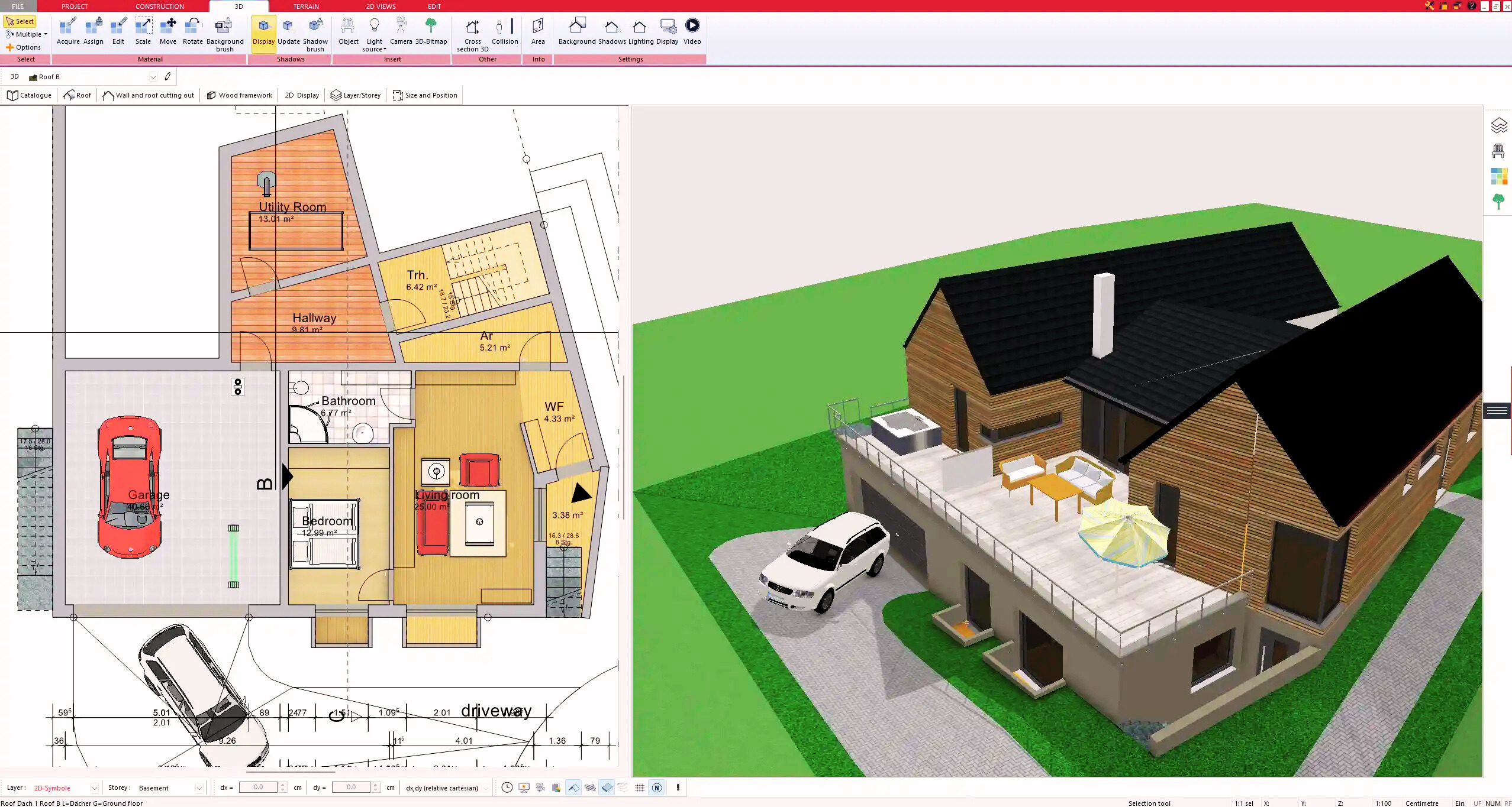
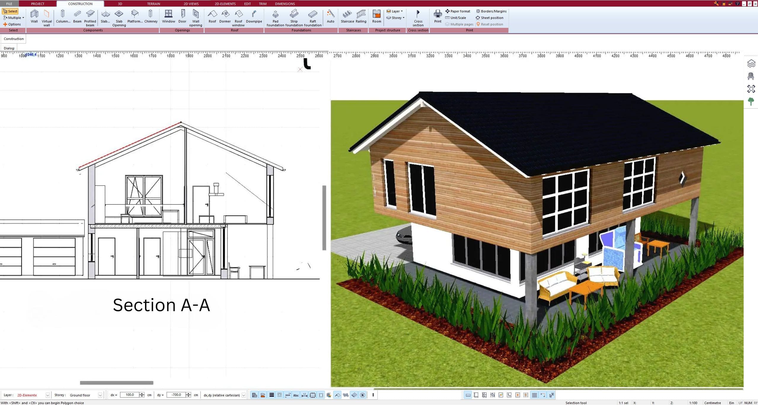
![How to Make Construction Drawings for a House]()
 What construction drawings actually need to do
Construction drawings are not presentation drawings. They are working documents. A 3D model or a beautiful floor plan might help you visualize the home, but the construction set has a different job. It needs to communicate dimensions, wall locations, floor heights, structural intent, openings, materials, and enough detail for permit review and construction pricing.
That does not mean every house plan needs the same level of detail. A simple one-story rectangular home will usually need fewer sheets and details than a custom home with multiple roof lines, retaining walls, and complex framing. The standard still stays the same: every drawing should reduce guesswork.
If a contractor keeps having to call and ask, “What did you mean here?” the drawing set is not finished yet.
How to make construction drawings for a house in the right order
The biggest mistake beginners make is starting with details before the core geometry is settled. Construction drawings should be built in layers, from broad decisions to fine information.
Start with the floor plan and overall dimensions
Begin with the layout itself. Establish exterior walls, interior partitions, room sizes, door swings, and window locations. At this stage, accuracy matters more than decoration. You are defining the physical structure of the house, not making a marketing brochure.
Use a consistent dimension strategy. Exterior walls should be dimensioned overall and to major openings or wall breaks. Interior plans should show enough dimensions to place partitions, doors, plumbing fixtures, and built-ins without relying on visual estimation. If dimensions conflict, crews usually follow the smaller chain dimensions over the larger overall dimension, so those numbers need to be checked carefully.
Add wall thicknesses, openings, and vertical information
Once the plan layout is stable, add actual wall assemblies, not just symbolic lines. A 2×4 interior wall, a 2×6 exterior wall, and a furred plumbing wall are not interchangeable in construction drawings. Their thickness affects room dimensions, framing, insulation, and how sections line up.
Then define doors and windows properly. That includes sizes, operation type where relevant, and placement that matches the elevations. A common error is changing a window on the floor plan and forgetting to update the exterior view. That creates confusion fast, especially during permit review.
You also need vertical control. Floor-to-ceiling heights, finished floor elevations, roof slopes, and foundation step-downs should not be left vague. A plan can look fine in 2D and still be impossible to build correctly if the heights are unresolved.
Build the drawing set sheet by sheet
Most house construction drawings include a site plan, foundation plan, floor plans, exterior elevations, building sections, roof plan, and at least some construction details. Depending on the project, you may also need framing plans, electrical layouts, plumbing information, schedules, energy notes, and code data.
This is where software can save a lot of time. A house planning program that links 2D drawings with a 3D model makes coordination much easier because changes to the plan can be checked across elevations, sections, and views before they become field problems. For users who want professional output without enterprise-level CAD complexity, that is often the difference between finishing a set and getting stuck halfway through.
The key drawings every house plan usually includes
Site plan
The site plan shows where the house sits on the lot. It typically includes property lines, setbacks, driveway, walkways, easements, north arrow, lot dimensions, and the building footprint. In many jurisdictions, this sheet is essential for permit review because it confirms zoning compliance.
If the lot slopes, topography or grade information may also be required. On a flat suburban lot, a simpler site plan may be enough. On a hillside or irregular parcel, this sheet becomes much more technical.
Foundation plan
The foundation plan shows footings, foundation walls, slab edges, piers, thickened slabs, and structural notes. This sheet needs close coordination with the floor plan above. If load-bearing walls on the floor plan do not align with support below, that issue needs to be resolved before construction begins.
For additions and remodels, foundation drawings often become more complicated because new and existing conditions must be clearly distinguished.
Floor plans
Floor plans are the backbone of the set. They show wall locations, room names, door and window tags, dimensions, stairs, cabinetry, plumbing fixtures, and any notes needed to explain construction intent. Each level of the house should have its own plan.
This is also where people tend to overload the drawing. If everything is shown on one sheet, readability suffers. Clean, organized plans are more useful than crowded ones.
Exterior elevations
Elevations show the outside faces of the house. They communicate wall heights, roof forms, window and door placement, finish materials, and grade relationship. Builders use them to understand massing and appearance. Permit offices use them to confirm height and design compliance.
Good elevations are not just traced views. They need notes and dimensions where necessary, especially when there are changes in siding, trim, roof pitch, or floor level.
Building sections and details
Sections cut through the house to show how it is assembled vertically. They clarify ceiling heights, roof build-up, floor structure, foundation depth, and how walls connect to other elements. Details zoom in further and explain specific conditions like eaves, stair construction, waterproofing transitions, or slab edges.
You do not need dozens of details for every project. But you do need enough to explain the tricky parts. If a condition is unusual, it should probably be drawn larger.
Common problems when making house construction drawings
The hardest part is usually not drawing the house. It is coordinating all the information so nothing contradicts itself.
One frequent issue is dimension drift. You adjust a room size, but forget to update the overall building width. Another is inconsistent symbols or labeling. Windows may be tagged one way on the plan and another way in the schedule. Roof slopes might appear in one place but not another.
There is also the question of how much detail is enough. Too little detail creates RFIs and field decisions. Too much detail can slow the process and bury critical information. The right level depends on project complexity, local permit requirements, and who will use the drawings. A contractor building from experience may need less explanation than a homeowner coordinating multiple subs directly.
How to make construction drawings for a house that are permit-ready
Permit-ready does not always mean engineer-ready or builder-ready in every jurisdiction. Local code departments vary. Some require structural notes, energy information, and highly specific code references. Others focus mainly on zoning, life safety, and basic construction data.
That is why your first step should always be checking local permit requirements before finalizing the set. Find out which sheets are required, whether stamped drawings are needed, and what format the submission must follow. Designing first and checking later can force a lot of rework.
It also helps to include basic code information directly in the set where appropriate. That may include occupancy type, construction type, gross floor area, egress information, smoke and CO detector placement, and insulation notes. Even when not strictly required on every project, this information makes the set more credible and easier to review.
Tools and workflow that make the process easier
You can make construction drawings by hand, with general CAD software, or with residential design software built specifically for house planning. For most homeowners, remodelers, and small professionals, purpose-built home design software is usually the practical middle ground. It provides enough technical control to create accurate plans, elevations, sections, and printable drawing sheets without forcing you into an overly complex drafting workflow.
That matters because speed is not just convenience. The faster you can revise layouts, update dimensions, test roof forms, and generate coordinated views, the more likely you are to catch mistakes early. Plan7Architect is a good example of that approach, especially for users who want serious house planning output with a one-time purchase instead of a costly subscription.
Still, software does not replace judgment. You need to decide what information belongs on the page, what needs clarification, and when a structural engineer or local design professional should review the work. Complex spans, unusual foundations, seismic requirements, and load-bearing changes are not areas for guesswork.
Final checks before you issue the drawing set
Before calling the drawings done, print them to scale and review them like a builder would. Check that the plans, elevations, and sections agree. Confirm door and window sizes. Make sure dimensions are readable and not duplicated carelessly. Look for missing notes at unusual conditions.
Most problems become obvious when you stop designing and start reading the set as instructions. If someone else had to build this house from your drawings alone, where would they hesitate?
That question usually leads to the last improvements that make a house plan truly buildable.
Plan your project with Plan7Architect
Plan7Architect Pro 5 for $139.99
You don’t need any prior experience because the software has been specifically designed for beginners. The planning process is carried out in 5 simple steps:
1. Draw Walls
2. Windows & Doors
3. Floors & Roof
4. Textures & 3D Objects
5. Plan for the Building Permit
6. Export the Floor Plan as a 3D Model for Twinmotion
- – Compliant with international construction standards
- – Usable on 3 PCs simultaneously
- – Option for consultation with an architect
- – Comprehensive user manual
- – Regular updates
- – Video tutorials
- – Millions of 3D objects available
Why Thousands of Builders Prefer Plan7Architect
Why choose Plan7Architect over other home design tools?