There are generally between 10 and 12 main types of construction drawings that are used in building projects. The exact number depends on the scale of the project, the requirements of the local authorities, and the level of detail demanded by the client. These drawings serve as the universal language between architects, engineers, contractors, and clients, ensuring that everyone has a clear understanding of the project. With modern software like Plan7Architect, you can create all these drawing types in both 2D and 3D, using either European metric units or American imperial units, depending on what you need.
Main Types of Construction Drawings
Site Plan
A site plan is one of the first drawings produced for any project. It shows the boundaries of the land, the placement of the building, access points such as roads and driveways, parking areas, utility connections, and landscape elements. It ensures that the building complies with zoning rules and aligns properly with its environment.
Key elements often included in a site plan:
-
Plot boundaries and dimensions
-
Roads, sidewalks, and driveways
-
Utility lines and connections
-
Drainage systems
-
Landscaping and outdoor features
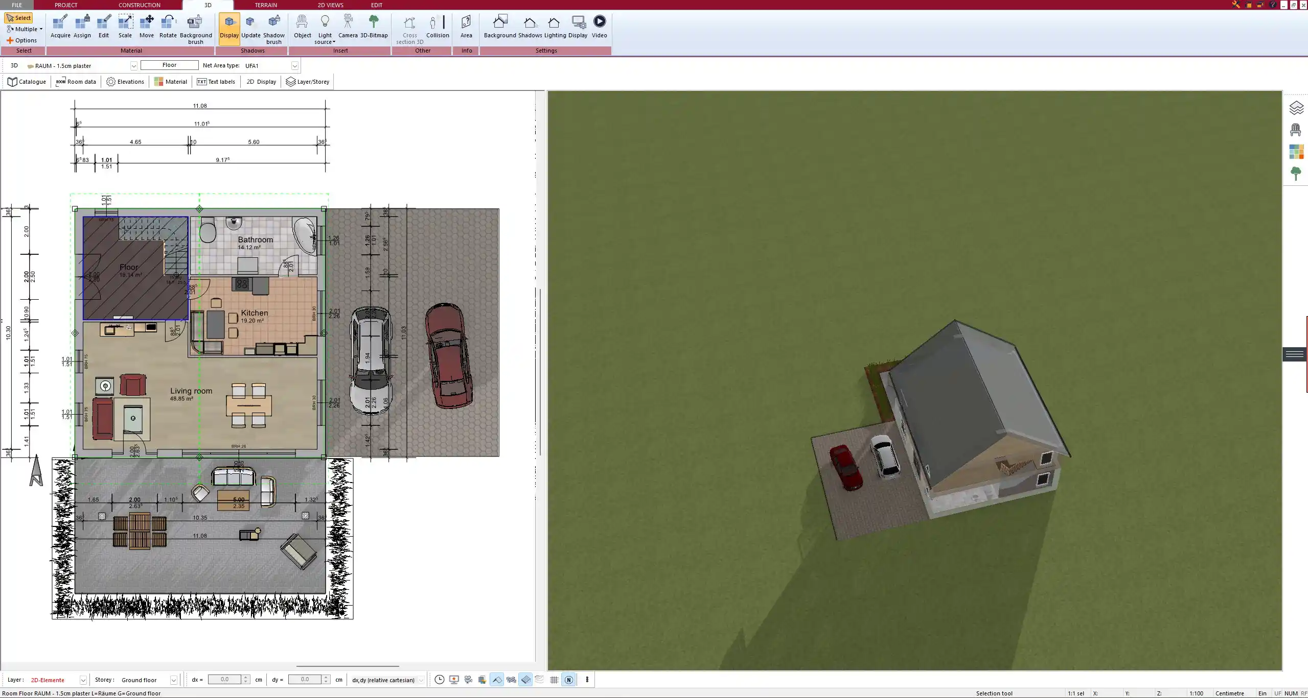
Floor Plans
A floor plan is a 2D representation of the interior layout. It displays walls, windows, doors, and how rooms are arranged. These drawings are essential for both design and construction since they guide builders and help clients visualize the space.
Floor plans usually include:
-
Room names and dimensions
-
Wall thicknesses
-
Door and window locations
-
Staircases
-
Furniture layouts in some cases
Elevations
Elevation drawings show the exterior of a building from all sides. They highlight architectural style, façade materials, and the relationship between floor levels and ground level.
Types of elevation drawings:
-
Front elevation
-
Rear elevation
-
Side elevations (left and right)
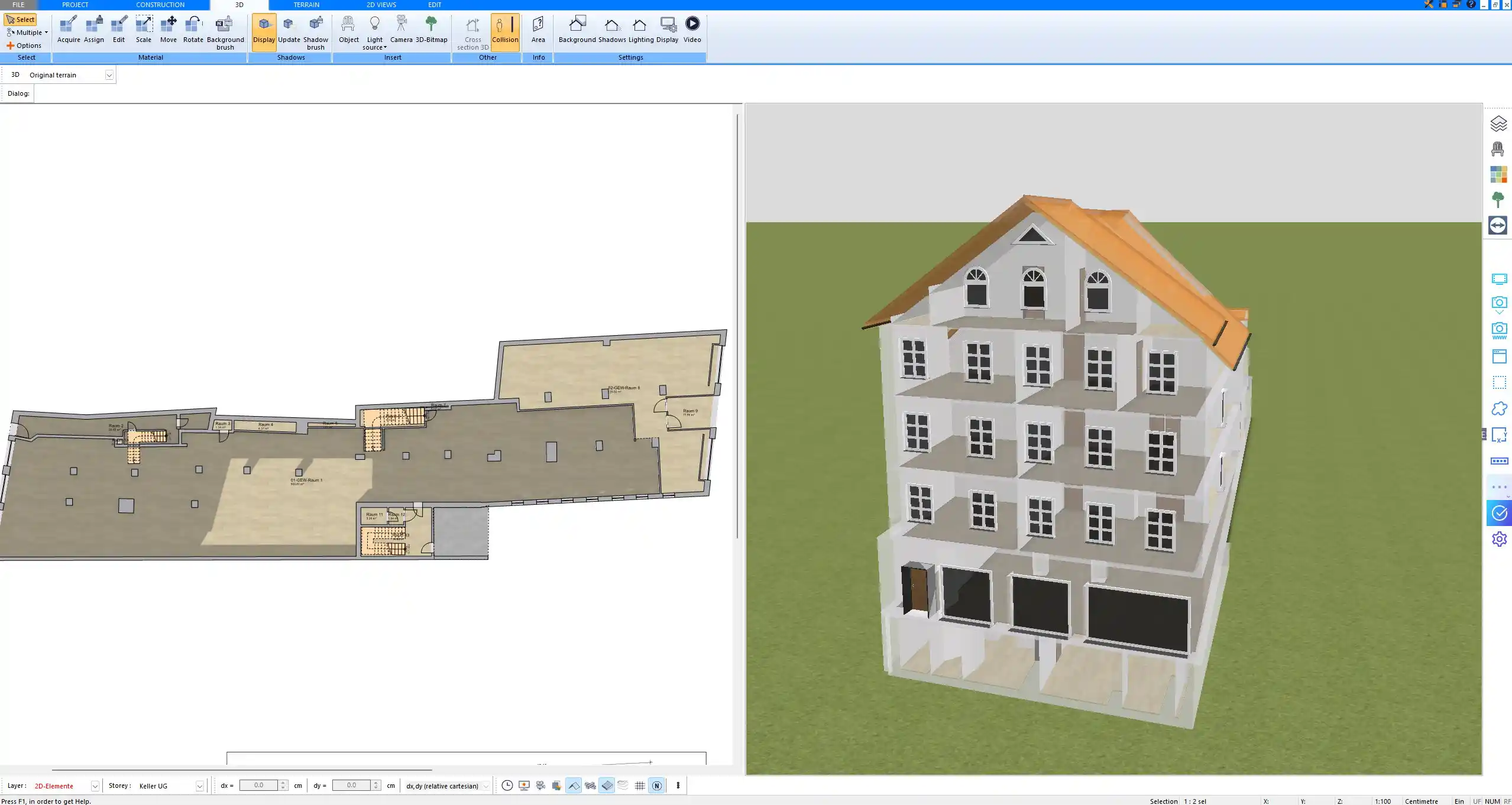
Sections
A section drawing is like cutting the building vertically to reveal the inside. It allows you to see floor levels, ceiling heights, staircases, and structural elements. Sections are crucial for understanding the vertical relationship between different building components.
Detail Drawings
Sometimes certain areas of a project are too complex to be fully understood in standard plans. Detail drawings provide enlarged views of elements such as staircases, window frames, or structural joints.
Examples of details often drawn separately:
-
Window-to-wall connections
-
Door frames
-
Staircase steps and railings
-
Roof truss connections
Structural Drawings
Structural drawings are prepared by civil or structural engineers. They provide exact information about load-bearing elements and reinforcements.
Information typically found in structural drawings:
-
Foundation plans
-
Column and beam details
-
Slab reinforcements
-
Load calculations
Electrical Drawings
Electrical drawings show the design of the electrical system within the building. They help electricians plan wiring and ensure safe and efficient installation.
Electrical drawings often include:
-
Power outlets and switches
-
Lighting fixtures
-
Circuit diagrams
-
Distribution boards
Plumbing and Sanitary Drawings
These drawings describe the water supply and drainage systems. They guide plumbers in installing pipes, connections, and fixtures.
Plumbing drawings typically cover:
-
Water supply lines
-
Drainage and sewage systems
-
Location of sinks, toilets, and showers
-
Hot water systems
HVAC Drawings
Heating, ventilation, and air conditioning systems are presented in HVAC drawings. They ensure that the building has proper airflow, heating, and cooling systems.
Common elements in HVAC drawings:
-
Duct layouts
-
Vent positions
-
Heating and cooling units
-
Air circulation flow
Finishing and Interior Drawings
These drawings show how the inside of the building will look once completed. They cover materials, textures, and colors used on walls, floors, and ceilings. Interior designers often rely on these drawings to finalize the aesthetics.
Examples of finishing details:
-
Flooring types
-
Ceiling designs
-
Wall finishes and textures
-
Built-in furniture
Landscape Drawings
Landscape drawings are used for gardens, outdoor areas, patios, and driveways. They show both hardscaping (paved surfaces, retaining walls) and softscaping (plants, lawns, trees).
As-Built Drawings
After construction is complete, as-built drawings are created to reflect the project exactly as it was built, including any changes made during construction. These drawings are valuable for future renovations, repairs, or property sales.
Why So Many Types?
Each type of construction drawing provides information to a different group of professionals. While a homeowner may be more interested in floor plans and elevations, contractors need structural, electrical, plumbing, and HVAC drawings to carry out the work correctly. Using all types reduces the risk of misunderstandings, prevents costly errors, and ensures compliance with legal requirements.
Who Uses These Drawings?
Construction drawings are not limited to one group of people; they are used by many parties throughout the project.
Main users of construction drawings:
-
Architects – for design and overall coordination
-
Structural engineers – for safety and load distribution
-
Contractors – for executing the building work
-
Interior designers – for selecting finishes and furniture placement
-
Clients – for understanding what the finished project will look like
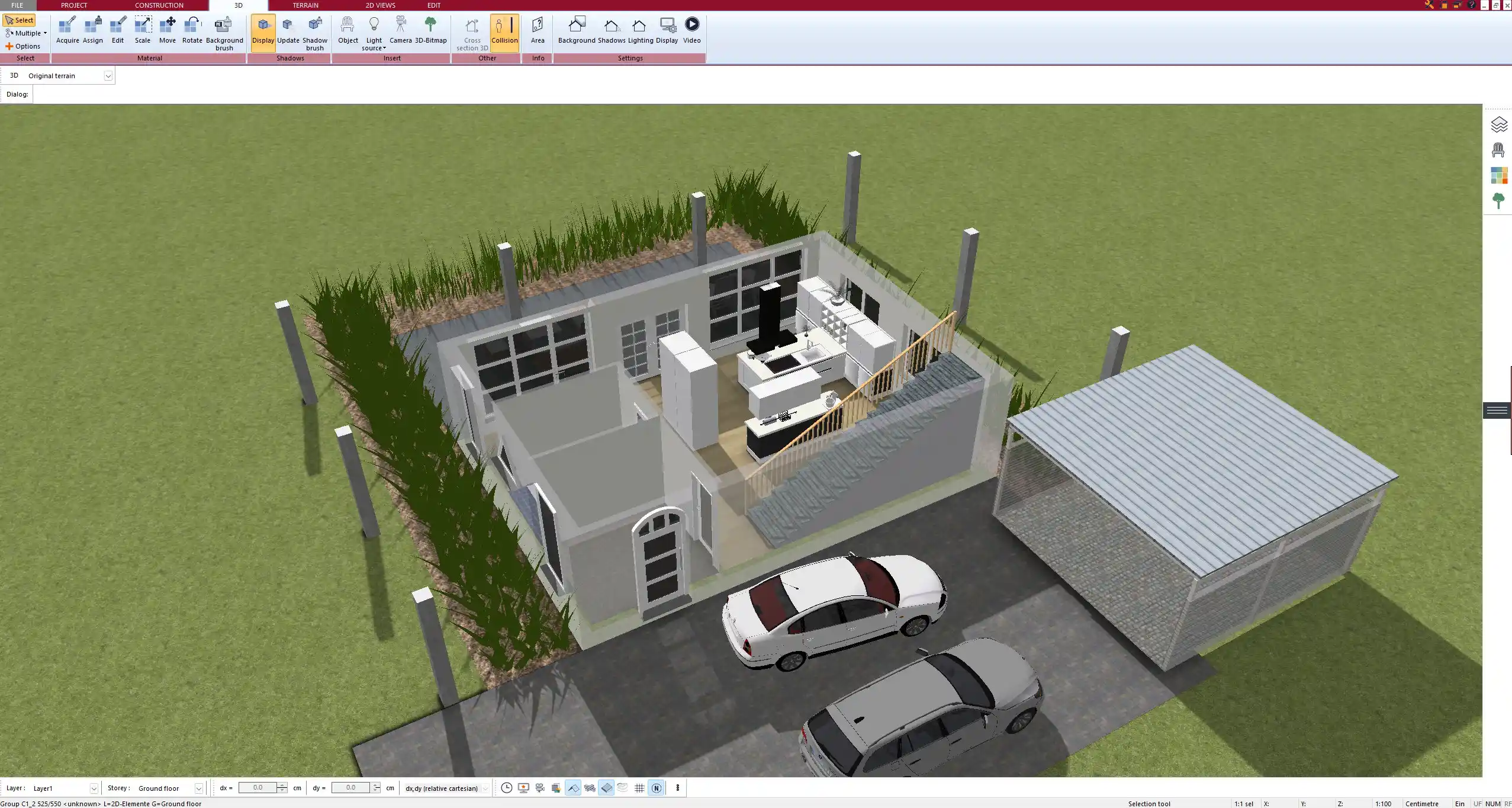
Digital Tools for Construction Drawings
With modern CAD software such as Plan7Architect, you can create all the above drawing types in both 2D and 3D. The advantage is that you can switch instantly between European metric units and American imperial units, which makes it suitable for international use. Real-time visualization, simple editing, and precise measurement functions allow you to plan more effectively and reduce mistakes before construction begins.
Common Questions
Do all projects need all types of drawings?
Not every project requires all drawing types. A simple home extension may only need site plans, floor plans, and elevations, while a large commercial building will demand a full set including HVAC, structural, and as-built drawings.
Are these drawings legally required?
In most countries, construction drawings are required for building permits and inspections. They provide proof that the project meets safety and zoning regulations.
What is the difference between a plan and a section?
A plan shows the building as if cut horizontally, providing a bird’s-eye view of the layout. A section is a vertical cut, showing what the interior looks like across different levels.
Plan Professional Floor Plans Yourself with Plan7Architect
With Plan7Architect you can create all types of professional construction drawings yourself, from site plans to detailed sections, structural layouts, and interior designs. The software allows you to work in both European metric units and American imperial units, giving you full flexibility for international projects. It is designed so that you can easily plan your building project with precision and realistic 3D views. Customers also benefit from a 14-day money-back guarantee, which replaces a trial version. You can simply cancel your purchase via email if you are not satisfied. This makes Plan7Architect the ideal choice if you want to create professional construction drawings on your own.
Plan your project with Plan7Architect

Plan7Architect Pro 5 for $109.99
You don’t need any prior experience because the software has been specifically designed for beginners. The planning process is carried out in 5 simple steps:
1. Draw Walls

2. Windows & Doors

3. Floors & Roof

4. Textures & 3D Objects

5. Plan for the Building Permit

6. Export the Floor Plan as a 3D Model for Twinmotion

- – Compliant with international construction standards
- – Usable on 3 PCs simultaneously
- – Option for consultation with an architect
- – Comprehensive user manual
- – Regular updates
- – Video tutorials
- – Millions of 3D objects available
Why Thousands of Builders Prefer Plan7Architect
Why choose Plan7Architect over other home design tools?