Construction drawings are organized into a set of sheets that follow a standardized order. The sequence typically begins with general information such as the title sheet, index, and notes. It then moves to site plans, floor plans, roof plans, elevations, sections, and structural drawings. After these, the set includes mechanical, electrical, and plumbing (MEP) layouts, as well as schedules and detailed construction drawings. This logical order ensures that every professional involved in the project can easily find the information needed.
Typical Sequence of Construction Drawings
Title and General Information
The first part of any construction drawing set contains:
-
A cover sheet with project name, address, client details, and designer or architect information
-
An index of all drawings included in the set
-
Legends, symbols, and general notes that apply throughout the drawings
This section gives you the overall framework so you understand what to expect in the rest of the drawings.
Site and Location Plans
Site and location plans show the placement of the building in its environment. These drawings often include:
-
Property boundaries
-
Orientation (north arrow)
-
Landscaping elements
-
Driveways and access roads
-
Utility connections
A location plan may also illustrate how the project fits into the wider area, such as its street context.
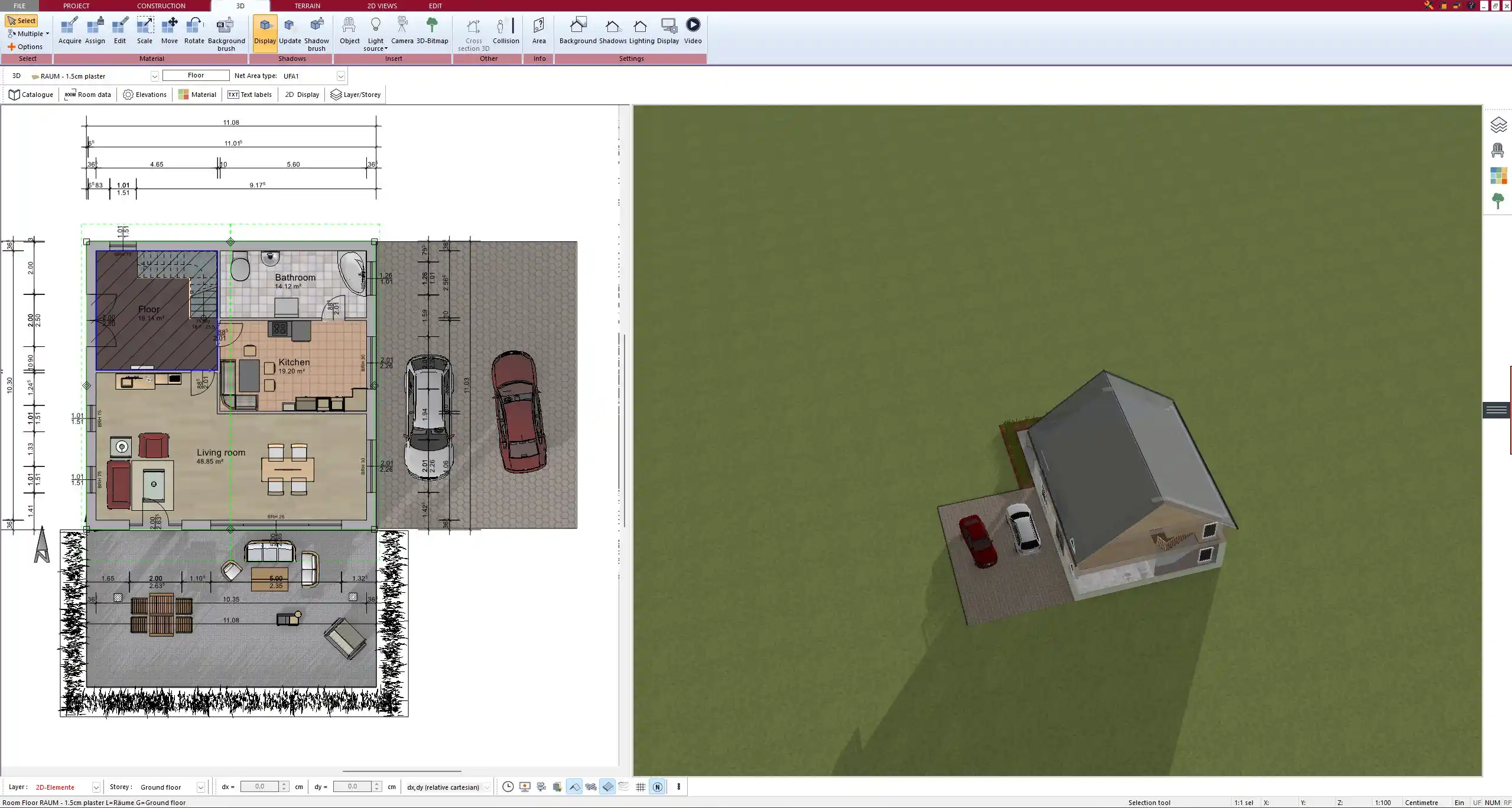
Floor Plans
Floor plans form the backbone of construction drawings. They are organized by level: basement, ground floor, upper floors. Each plan includes:
-
Accurate dimensions of rooms, walls, and openings
-
Room names and usage labels
-
Locations of doors, windows, and staircases
-
Wall types and thicknesses
When working with measurements, floor plans can be prepared in both metric (millimeters, centimeters, meters) and imperial (inches, feet) systems. In modern CAD software like Plan7Architect, you can switch between these units depending on your regional standard.
Elevations and Sections
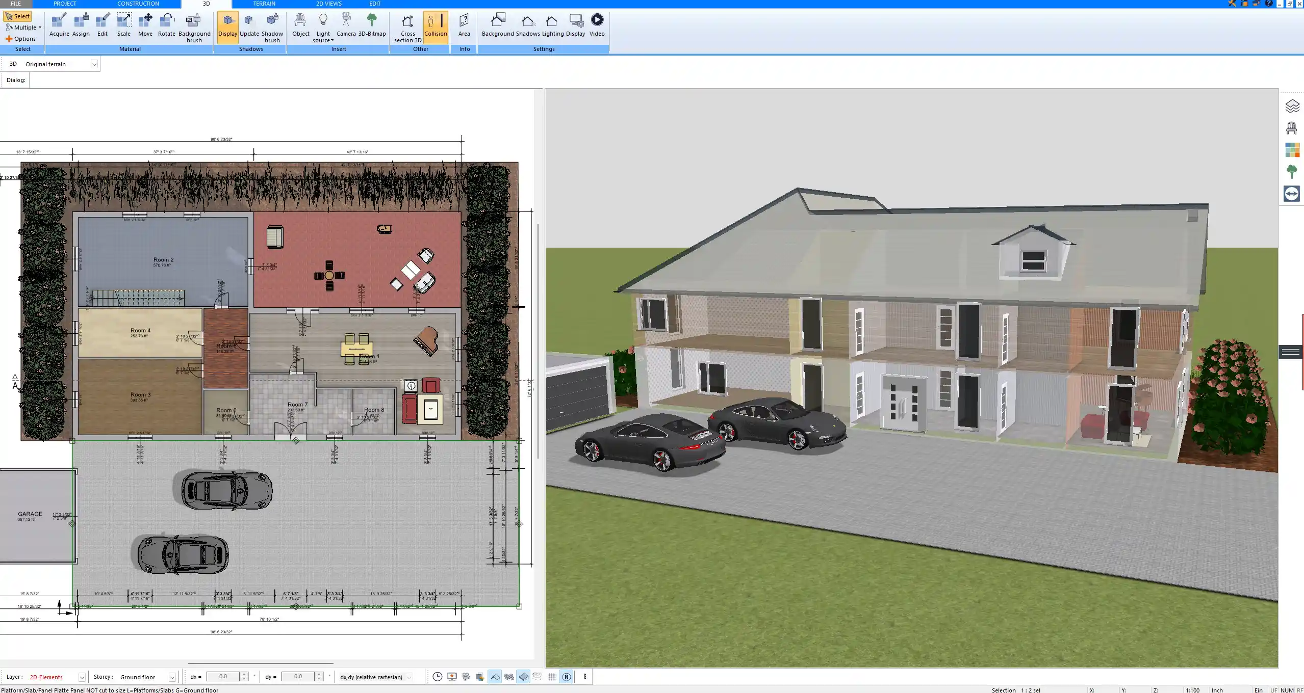
Elevations provide exterior views of the building from each side: front, rear, left, and right. They show façade design, window placements, roof slopes, and exterior finishes.
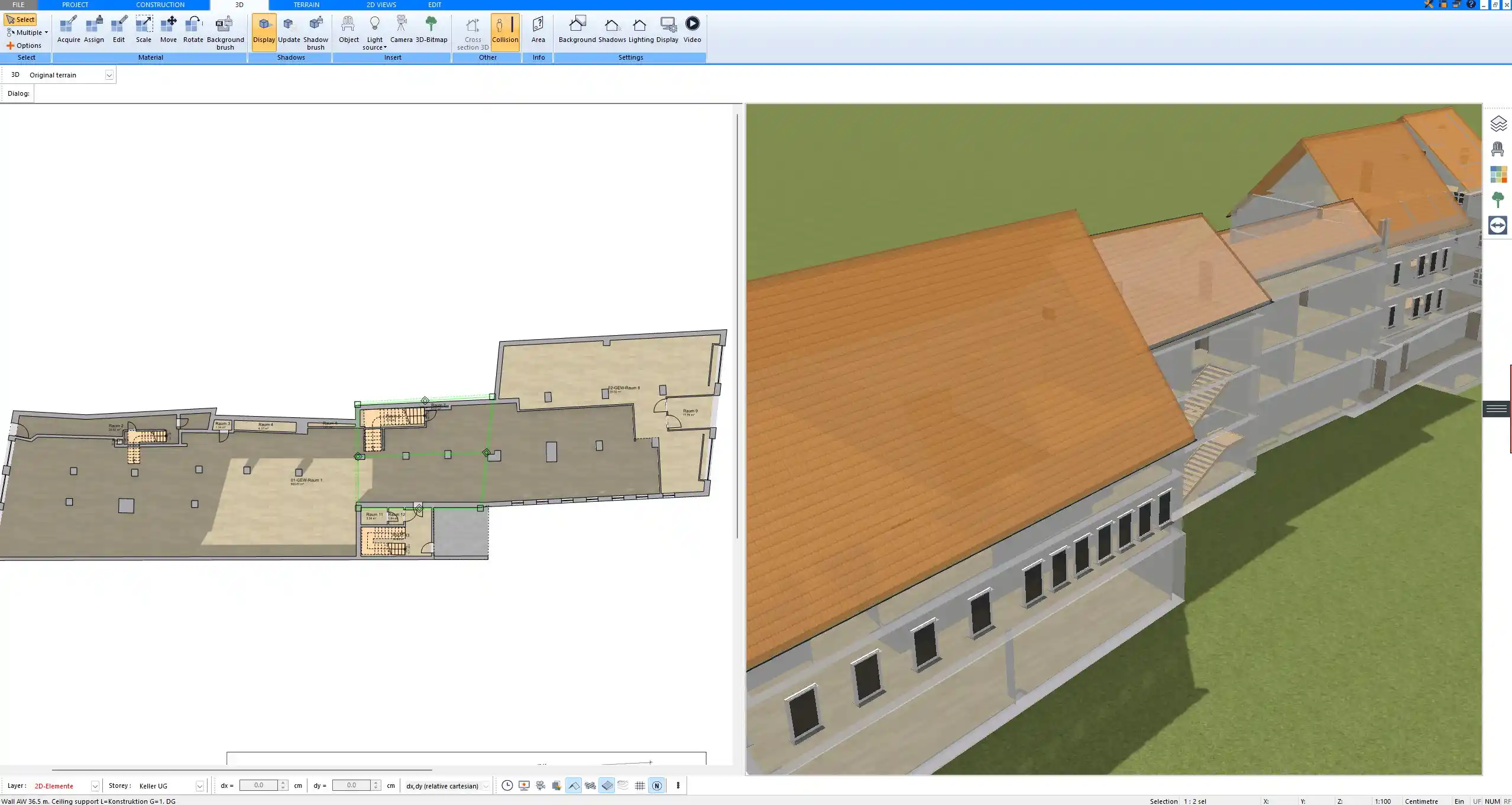
Sections, on the other hand, are vertical cuts through the building. They illustrate how different levels connect, show ceiling heights, stair construction, and structural components.
Structural Drawings
Structural drawings highlight the elements that carry loads and provide stability. These may include:
-
Foundation plans
-
Framing layouts for floors and roofs
-
Reinforcement details for concrete elements
They are usually prepared by structural engineers but are part of the complete drawing package.
Mechanical, Electrical, and Plumbing (MEP)
MEP drawings are critical for the technical systems of a building. They include:
-
HVAC layouts showing ducts, vents, and mechanical equipment
-
Electrical diagrams with lighting, outlets, and wiring systems
-
Plumbing layouts with water supply lines, drainage, and fixture placements
These plans ensure that the essential systems are properly coordinated with the architecture.
Schedules and Details
Schedules summarize detailed information in table form. Common examples are:
-
Door schedules listing size, type, and hardware
-
Window schedules with dimensions and glazing types
-
Finish schedules specifying flooring, wall treatments, and ceilings
Construction details show specific assemblies at a larger scale, such as staircases, wall junctions, or roof edges.
Standards and Conventions
Construction drawings usually follow national or international standards. In the U.S., the CSI (Construction Specifications Institute) guidelines are common, while in Europe standards such as DIN or BS are widely used.
Sheets are often labeled with prefixes that identify their category:
-
A for Architectural
-
S for Structural
-
M for Mechanical
-
E for Electrical
-
P for Plumbing
Line weights, hatching styles, and symbols are kept consistent across the set so that the drawings remain clear and professional.
Digital Organization of Drawings
In CAD and BIM software, construction drawings are organized into layers. Layers separate elements such as walls, dimensions, furniture, and electrical systems, allowing you to switch them on and off as needed. This helps keep complex projects manageable.
Digital software also allows you to switch between metric and imperial units, export professional plans as PDFs, or share in formats like DWG or DXF for collaboration with other professionals.
Why Organization Matters
Proper organization of construction drawings reduces errors, saves time, and ensures that every professional on the project works from the same information. When drawings are structured logically, contractors can build more efficiently, architects can coordinate with engineers, and permitting authorities can quickly review the documents.
Create Professional Floor Plans with Plan7Architect
With Plan7Architect, you can create professional floor plans and complete drawing sets just as described above. The software allows you to prepare site plans, floor layouts, elevations, sections, and even MEP layouts, all organized clearly and ready for use. You can switch between European metric units and American imperial units, depending on your needs. If you are looking for a straightforward yet professional solution to create construction drawings, Plan7Architect is the right choice. You also have a 14-day money-back guarantee, which replaces a trial version. If you are not satisfied, you can easily cancel your purchase via email. This makes it completely risk-free for you to get started.
Plan your project with Plan7Architect

Plan7Architect Pro 5 for $109.99
You don’t need any prior experience because the software has been specifically designed for beginners. The planning process is carried out in 5 simple steps:
1. Draw Walls

2. Windows & Doors

3. Floors & Roof

4. Textures & 3D Objects

5. Plan for the Building Permit

6. Export the Floor Plan as a 3D Model for Twinmotion

- – Compliant with international construction standards
- – Usable on 3 PCs simultaneously
- – Option for consultation with an architect
- – Comprehensive user manual
- – Regular updates
- – Video tutorials
- – Millions of 3D objects available
Why Thousands of Builders Prefer Plan7Architect
Why choose Plan7Architect over other home design tools?