If you want to create a section drawing (also known as a vertical cut or cross-section) of your house, Plan7Architect makes it easy and accurate. You simply draw a section line across your floor plan, and the software automatically generates a vertical cut through your building. This view reveals the internal structure, such as wall layers, floor thicknesses, ceiling heights, stairs, and roof design.
You can switch to section view with just one click, adjust the viewing direction, and add height markers, annotations, or material labels. Plan7Architect supports both metric (meters, centimeters) and imperial (feet, inches) units—you can easily select the one you prefer in the software settings.
If you already have a floor plan ready, you can generate a professional-looking house section drawing in just a few minutes.
Step-by-Step – Drawing a Section View in Plan7Architect
1. Set up your floor plan
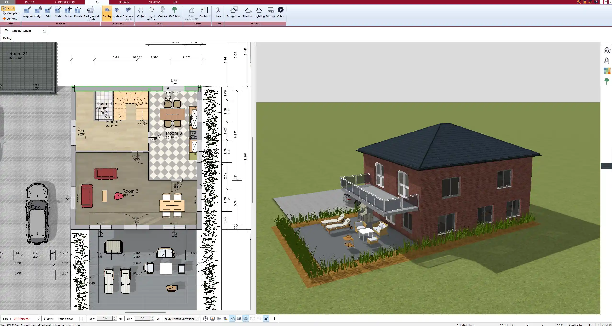
Before creating a section, you need a floor plan as the base. In Plan7Architect, you can either import an existing plan (PDF, image, or DXF) or draw one from scratch using the built-in 2D tools.
Start by outlining exterior and interior walls. Add structural elements such as doors, windows, and staircases. You can work on multiple floors by creating building layers for the basement, ground floor, upper floors, or attic.
To keep things organized:
Tip:
Create each level on a separate layer to manage vertical relationships easily in the section view later.
2. Switch to Section View mode
Once your floor plan is complete, go to the section tool in the toolbar. This mode allows you to draw a section line across your plan.
Click and drag to place a straight line where you want the vertical cut. You can place the line through staircases, bathrooms, or living spaces—wherever you want to show structural or spatial relationships.
You can also:
-
Adjust the direction of the view (which side is visible)
-
Change the cut depth (how far beyond the line elements are shown)
-
Rename the section for easier documentation (e.g., “Section A-A”)
3. Generate and edit the section
As soon as the section line is placed, Plan7Architect automatically generates a vertical cross-section of your house. This includes all elements intersected by the line, such as:
-
Floor and ceiling structures
-
Wall compositions with layers (e.g., insulation, masonry, plaster)
-
Stairs with risers and treads
-
Roof slopes and attic space
-
Window and door elevations
-
Furniture or fixtures in the cut area
You can click into the section view and begin customizing the display:
Table: Editable Features in Section View
| Element Type | Editable Options |
|---|---|
| Walls | Layer thickness, material display |
| Floors/Ceilings | Height, composition, cut line style |
| Roof | Pitch angle, overhangs, structural layers |
| Windows/Doors | Reveal depth, sill height |
| Dimensions | Vertical or horizontal, auto or manual |
You can choose a simple black-and-white outline or a color-coded section with material hatching to emphasize details.

4. Add dimensions and labels
After generating the basic section, it’s important to annotate your drawing properly. This makes it readable for contractors, authorities, or clients.
You can add:
-
Floor-to-ceiling heights
-
Finished floor levels (FFL)
-
Roof ridge heights
-
Room names or purposes
-
Material designations (e.g., “insulated concrete,” “wood beam”)
You can insert these annotations manually or activate auto-dimensioning tools.
Plan7Architect allows you to choose the unit system that suits your region: metric or imperial. So whether you prefer measurements like 2.50 m or 8 ft 2 in, the software displays them correctly.
Tip:
Use consistent unit settings for the entire project to avoid confusion during communication with planners or construction teams.
5. Export or print your section drawing
Once your section drawing is complete, you can export it for further use. Whether you need to submit it for permits, include it in a project presentation, or print it for on-site reference—Plan7Architect offers flexible output options.
Export formats include:
-
High-resolution image (PNG, JPG)
-
PDF (for official submissions)
-
DWG/DXF (for use in CAD programs)
-
Direct print layout with title blocks and scale bars
You can scale the drawing, add your company or personal details, and configure the layout to match architectural standards.
What Is a House Section Drawing and Why Is It Important?
A house section drawing shows a vertical slice through a building, typically from foundation to roof. It is one of the core architectural drawings used in construction and design.
It reveals:
-
Room heights and vertical spatial relationships
-
Structural connections between floors and roof
-
Wall and floor build-ups
-
Openings like doors and windows in elevation
-
Staircases and multi-level transitions
Unlike a floor plan, which shows the layout from above, a section helps understand height, construction layers, and vertical alignment. That makes it essential for technical planning, structural assessment, and visualizing the design in a more realistic way.
Section drawings are often required for:
-
Structural engineering checks
-
Communication between architects and tradespeople
-
Interior planning and lighting analysis

Features of Plan7Architect That Make Section Drawing Easy
I’ve worked with multiple design tools, and one of the reasons I prefer Plan7Architect is how intuitive it makes section planning. Even if you’re not a trained architect, you can create highly professional section drawings.
Some key features include:
-
Automatic section generation from any 2D floor plan
-
Live 3D visualization while adjusting the section line
-
Flexible cut line positioning (horizontal or angled)
-
Material layer visualization (with or without color/hatching)
-
Drag-and-drop annotations and dimensions
-
Easy unit conversion between metric and imperial
-
Real-time updates: change a wall or ceiling in the plan, and the section updates automatically
You can also save multiple sections in one project—ideal for complex buildings.
Pro Tips for Better Section Drawings
From experience, here are some practical suggestions to improve the clarity and usefulness of your house section drawings:
Tip Box: Helpful Tips for Section Drawing
-
Draw the section through critical parts of the building (stairs, split levels, roof structures)
-
Use contrasting line weights to separate cut elements (thicker) from background elements (thinner)
-
Place dimensions and labels outside the building cut for clarity
-
Add elevation markers and symbols like “Section A-A” to match your floor plan
-
Use transparency for certain elements if the view is too crowded
Ideal Use Cases – Who Needs Section Drawings?
House section drawings are not only for architects. They are extremely useful for anyone involved in a building project.
Use Cases:
-
Private home builders
To understand ceiling heights, window positions, and attic spaces -
Architectural designers
For design development, permit applications, and construction documents -
Construction companies
To plan wall assemblies, slab elevations, and roof detailing -
Interior designers
To assess room volumes, lighting, and vertical décor elements -
Inspectors and engineers
For evaluating code compliance, insulation, and structural performance
Whether you’re planning a simple one-story home or a multi-level villa, section drawings are an essential part of the process. Plan7Architect gives you all the tools to create them—clearly, quickly, and professionally.
Plan your project with Plan7Architect

Plan7Architect Pro 5 for $119.99
You don’t need any prior experience because the software has been specifically designed for beginners. The planning process is carried out in 5 simple steps:
1. Draw Walls

2. Windows & Doors

3. Floors & Roof

4. Textures & 3D Objects

5. Plan for the Building Permit
6. Export the Floor Plan as a 3D Model for Twinmotion

- – Compliant with international construction standards
- – Usable on 3 PCs simultaneously
- – Option for consultation with an architect
- – Comprehensive user manual
- – Regular updates
- – Video tutorials
- – Millions of 3D objects available