Construction drawings are the backbone of every building project, ensuring that architects, engineers, contractors, and clients have a common understanding of the design. The main types of construction drawings include:
-
Site Plan – placement of the building, boundaries, landscaping, utilities
-
Floor Plan – top view of layout, walls, doors, windows, dimensions
-
Elevation Drawing – exterior views of façades, building height, finishes
-
Section Drawing – cut-through views of the structure, showing how components connect
-
Detail Drawing – enlarged drawings of specific parts, such as stairs or joints
-
Structural Drawing – reinforcements, load-bearing elements, foundations
-
MEP Drawings (Mechanical, Electrical, Plumbing) – system layouts
-
Finishing Drawings – materials, fixtures, colors for interiors and exteriors
-
Shop Drawings – fabrication details prepared by contractors
-
As-Built Drawings – final record of the project after completion
These are the fundamental categories, and each has its own role in making sure a project is built exactly as planned.
Site Plan
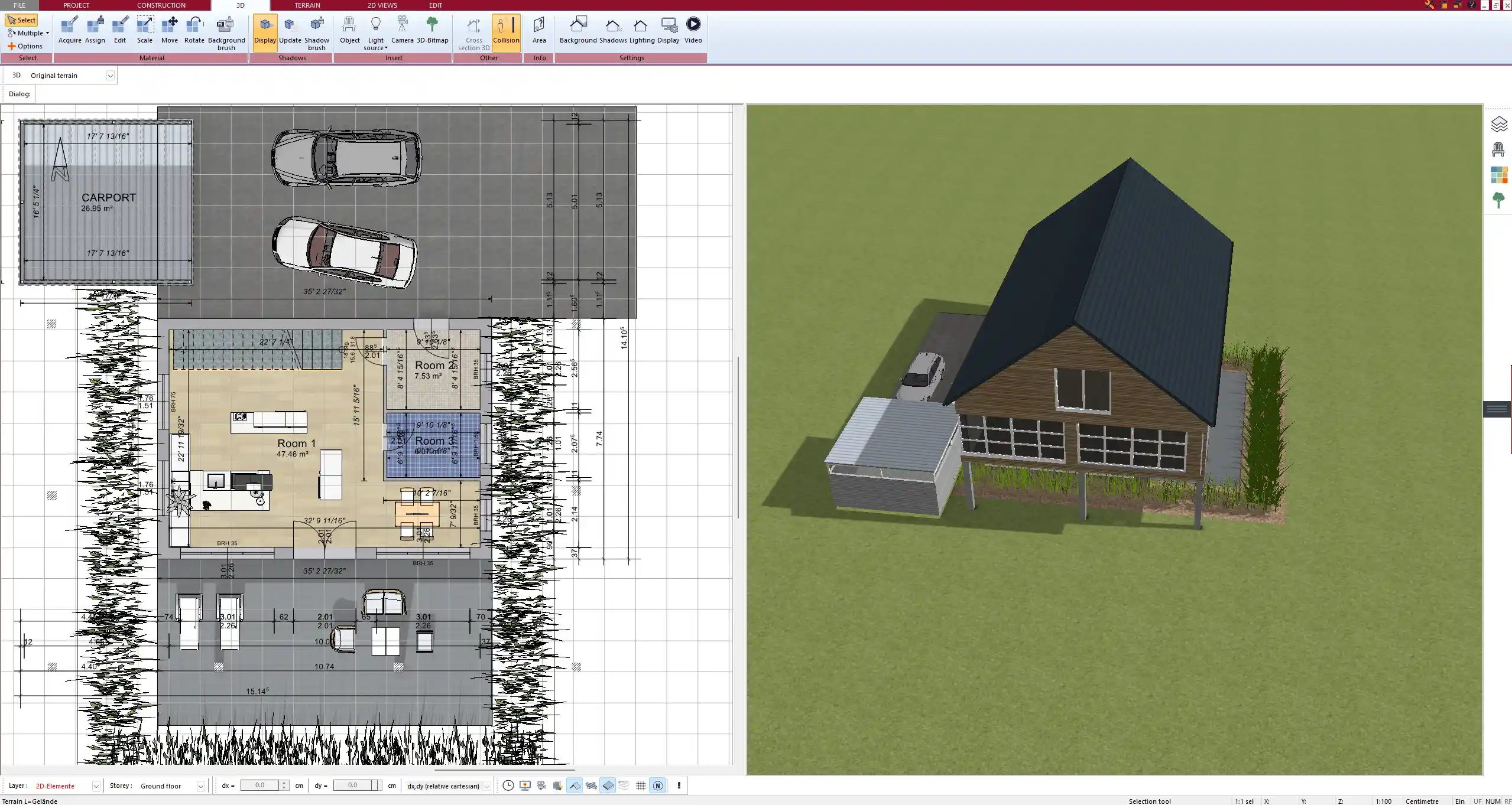
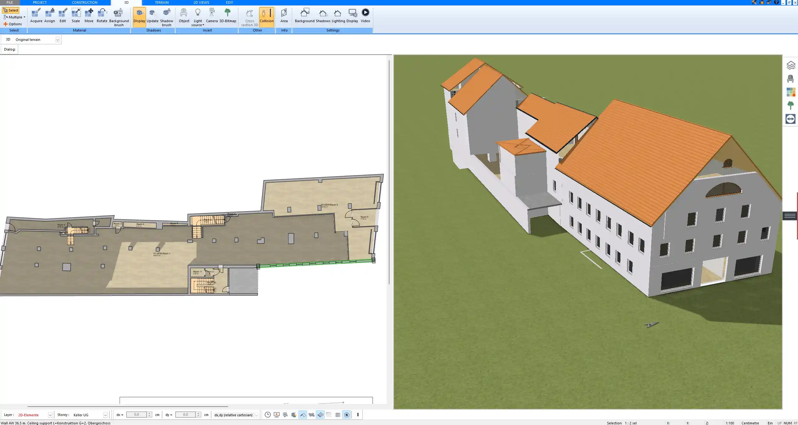
A site plan shows the overall position of a building on its plot of land. It includes property boundaries, orientation, access roads, neighboring buildings, landscaping, parking, and utility connections. In my own projects, this drawing was essential for discussions with local authorities and to plan the flow of vehicles and people. A site plan is also crucial for compliance with zoning rules and to prevent disputes with neighbors.
Floor Plan
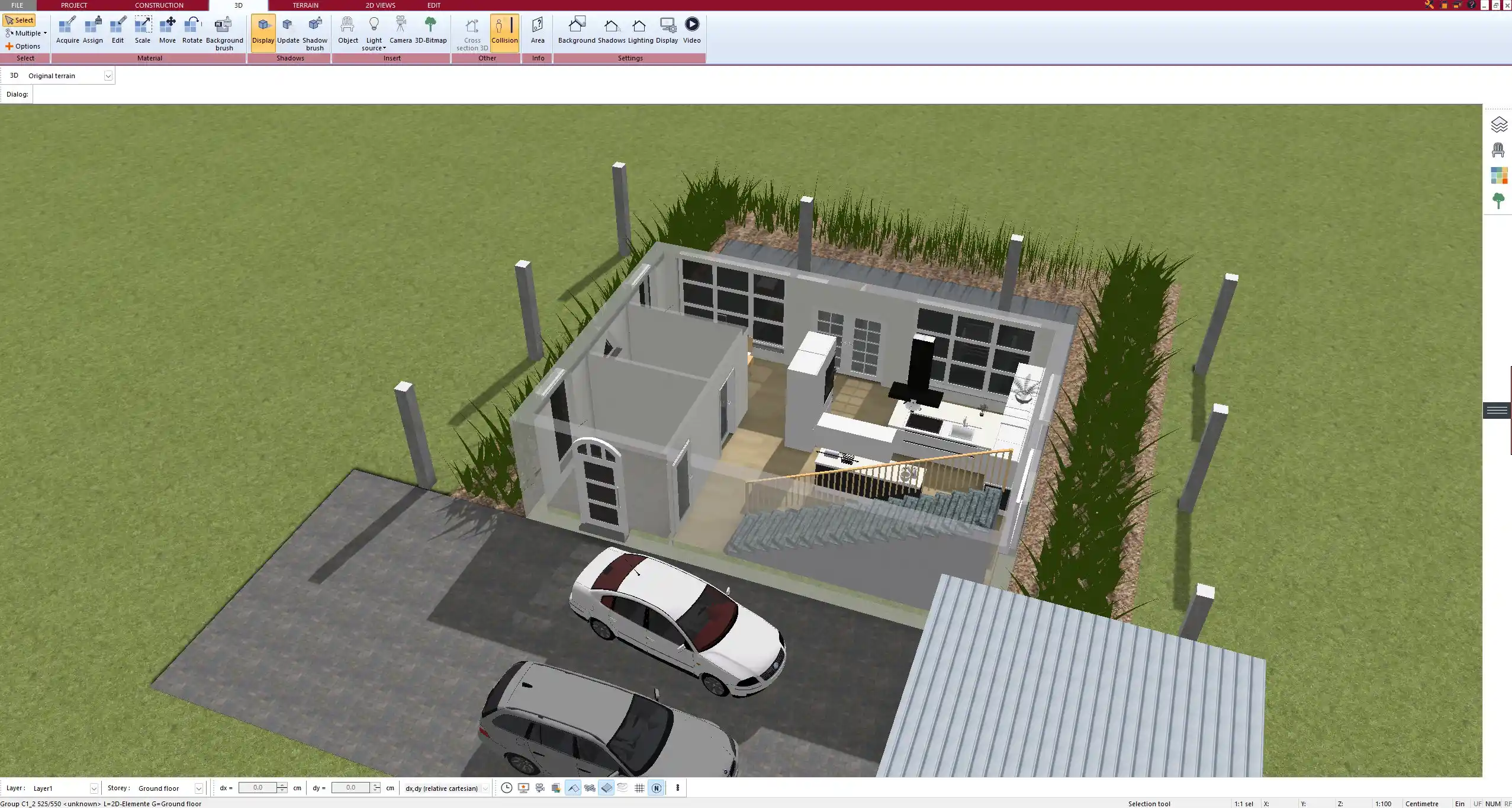
A floor plan gives a top-down view of the building layout. It shows room dimensions, wall thickness, placement of doors and windows, and sometimes furniture. For example, I often used floor plans to decide where to place my kitchen or bathroom and to verify that circulation between rooms worked well. Floor plans are the most familiar type of drawing for clients, since they can easily imagine themselves moving through the space.
Elevation Drawings
Elevations show the vertical face of each side of a building. They provide information about façade design, exterior finishes, window placements, and roof slopes. I found elevations particularly useful when comparing design options, such as choosing between different cladding materials or deciding how tall the building should be in relation to the street.
Section Drawings
A section drawing cuts through the building to reveal the structure inside. These are critical to understand how walls, floors, ceilings, and roofs are built. In practice, sections are what helped me coordinate with engineers and builders, because they expose details that cannot be seen in floor plans or elevations.
Detail Drawings
Detail drawings enlarge a specific component, such as a staircase, a window joint, or a structural connection. When I was working on projects with custom elements, detail drawings ensured that contractors knew exactly how to fabricate and assemble parts. Without them, mistakes would have been very costly.
Structural Drawings
Structural drawings are prepared by engineers and focus on the framework of the building. They specify the materials, load-bearing walls, columns, beams, foundations, and reinforcements. For residential projects, these drawings provided confidence that the house would be safe and stable.
MEP Drawings (Mechanical, Electrical, Plumbing)
MEP drawings cover technical systems that are invisible once construction is finished. They include heating and cooling ducts, electrical circuits, and water and sewage lines. Having clear MEP drawings avoids conflicts between systems, such as a ventilation duct blocking a plumbing line.
Finishing Drawings
Finishing drawings specify the final look of the building. They include wall finishes, flooring, ceilings, lighting fixtures, paint colors, and even small decorative details. When I renovated a property, these drawings gave me a clear overview of how the interior would look once complete and allowed me to choose finishes confidently.
Shop Drawings
Shop drawings are prepared by contractors or manufacturers to show how specific elements will be produced and installed. Examples include cabinetry, HVAC ducts, or steel frames. In one of my projects, the cabinetry shop drawings were key to ensuring that the furniture fit perfectly into the designed space.
As-Built Drawings
As-built drawings are created at the end of a project to show what was actually built. They record all modifications and changes made during construction. These drawings are extremely valuable for future renovations, repairs, or maintenance because they provide a reliable reference.
Why Construction Drawings Are Important
Construction drawings ensure that everyone involved in a project understands the design, technical requirements, and final goals. They reduce misunderstandings, provide legal documentation, and support compliance with building regulations. Without them, projects risk delays, errors, and disputes.
Tips for Working with Construction Drawings
-
Always verify the scale of the drawing (both metric and imperial units are commonly used; in Plan7Architect you can switch between European and American units).
-
Use consistent symbols and clear labels.
-
Update drawings whenever design changes occur.
-
Keep both digital and printed copies accessible to the project team.
Tip: When reviewing drawings, always cross-check dimensions between different drawing types (for example, floor plan and section). This helps identify mistakes early.
Using Software for Construction Drawings
Modern CAD software makes it easier to create, edit, and manage different types of construction drawings. With Plan7Architect, for example, you can design accurate 2D floor plans, generate elevations, sections, and even full 3D visualizations instantly. Automatic dimensioning, export formats like DWG, DXF, and PDF, and real-time 3D visualization provide efficiency and precision. The software also allows you to work in both European metric units and American imperial units, making it suitable for international projects.
Professional Floor Plans with Plan7Architect
With Plan7Architect, you can create all the construction drawing types mentioned above – from site plans to detailed sections and interior finish layouts. The software is intuitive to use, yet powerful enough to deliver professional results. You can freely switch between metric and imperial units, which makes it perfect whether you are planning a home in Europe or North America. If you want to design your own project or prepare accurate plans for collaboration with professionals, this program gives you full control. Customers benefit from a 14-day right of withdrawal, allowing you to cancel your purchase easily via email if needed. This replaces a trial version and lets you test the software without risk.
Plan your project with Plan7Architect

Plan7Architect Pro 5 for $109.99
You don’t need any prior experience because the software has been specifically designed for beginners. The planning process is carried out in 5 simple steps:
1. Draw Walls

2. Windows & Doors

3. Floors & Roof

4. Textures & 3D Objects

5. Plan for the Building Permit

6. Export the Floor Plan as a 3D Model for Twinmotion

- – Compliant with international construction standards
- – Usable on 3 PCs simultaneously
- – Option for consultation with an architect
- – Comprehensive user manual
- – Regular updates
- – Video tutorials
- – Millions of 3D objects available
Why Thousands of Builders Prefer Plan7Architect
Why choose Plan7Architect over other home design tools?