When preparing construction drawings, the following elements must always be included:
-
Title page with project details
-
Site plan with property boundaries, orientation, landscaping, and utilities
-
Floor plans for all levels with accurate dimensions, wall types, and room labels
-
Elevations showing all sides of the building with heights and exterior details
-
Sections showing cut-through views of structure and materials
-
Details of critical components such as windows, doors, stairs, and roof connections
-
Structural drawings for foundation, framing, beams, and columns
-
MEP drawings covering mechanical, electrical, and plumbing layouts
-
Schedules for windows, doors, and finishes
-
Notes, symbols, and legends for clarity
-
Code compliance annotations and revision block
Why a Checklist Matters
A construction drawing checklist helps ensure that no critical detail is overlooked. It keeps the documentation complete, avoids costly mistakes during construction, and improves communication between architects, contractors, engineers, and clients. It also serves as a reliable reference for legal and contractual purposes.
Detailed Breakdown of Checklist Items
Title Page
The title page should always provide:
-
Project name and location
-
Client and designer or architect details
-
Drawing index with sheet numbers
-
Scale used in the drawings
-
Date and revision information
Site Plan
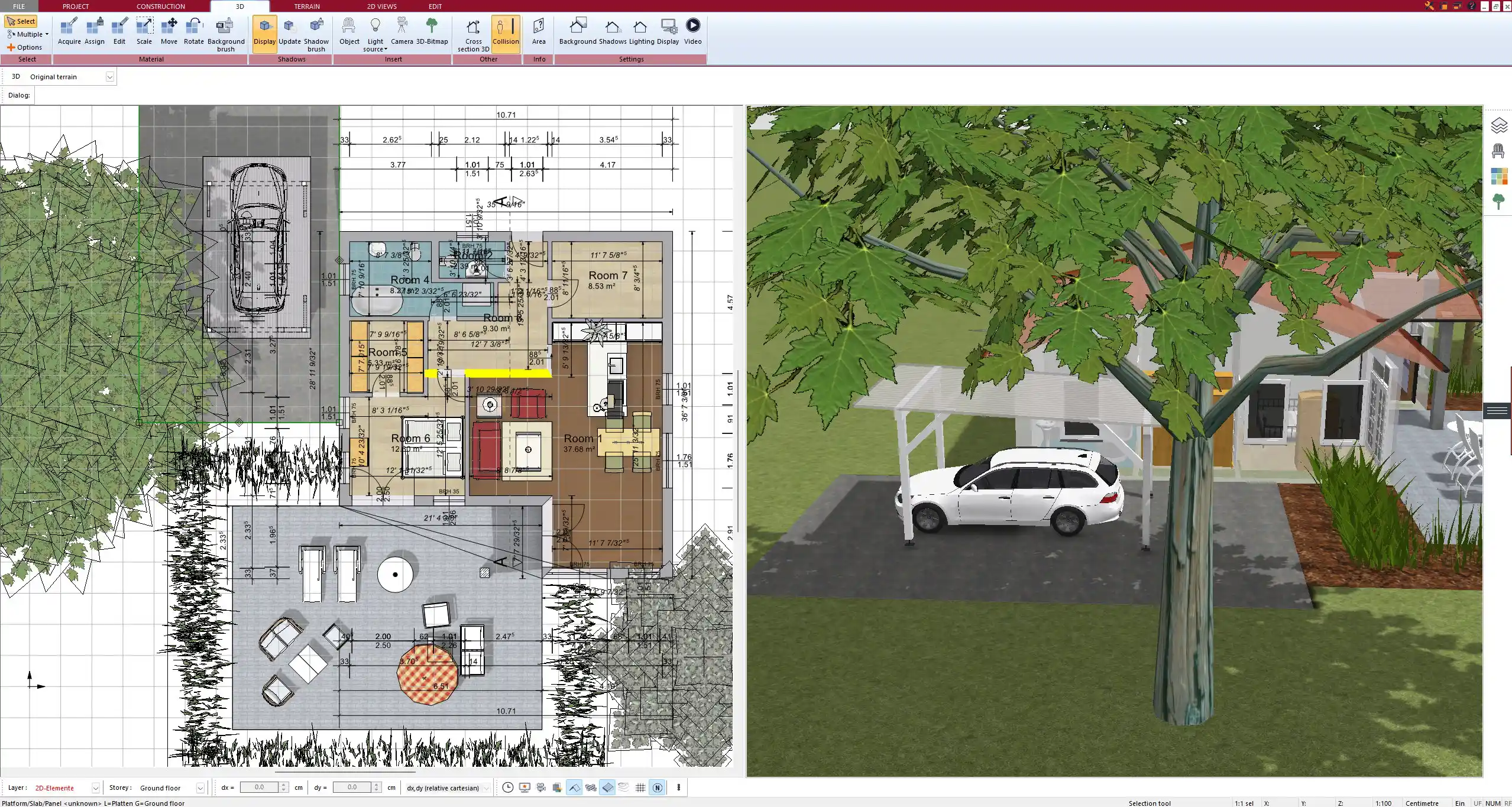
A site plan shows the building in context. It includes property lines, setbacks, orientation, driveways, and landscaping. Utilities such as water, electricity, and drainage must be indicated. Topography and slopes are often marked. Depending on the region, areas can be listed in both square meters and square feet.
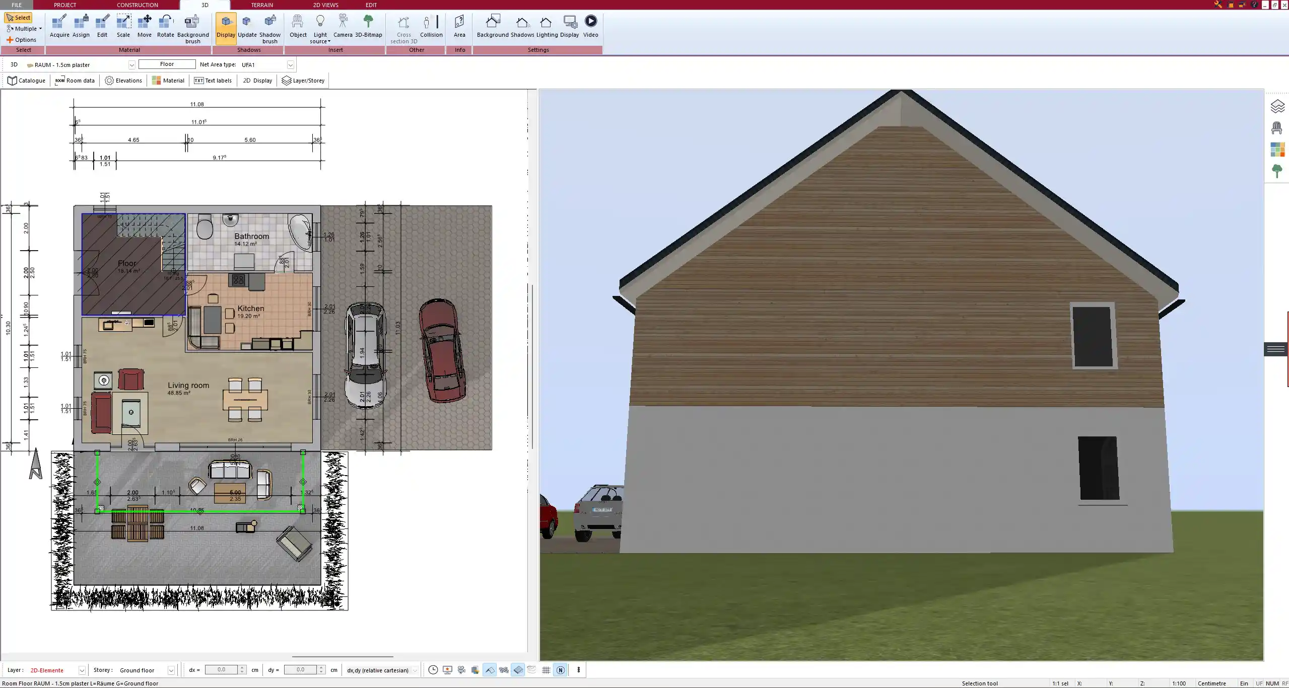
Floor Plans
Floor plans display the internal layout of each level. They should include:
-
Interior and exterior walls with thicknesses
-
Locations of doors and windows
-
Staircases and circulation areas
-
Dimensions for each room
-
Labels identifying room functions (kitchen, bathroom, living room, etc.)
A well-dimensioned floor plan is essential for both builders and clients to understand the design.
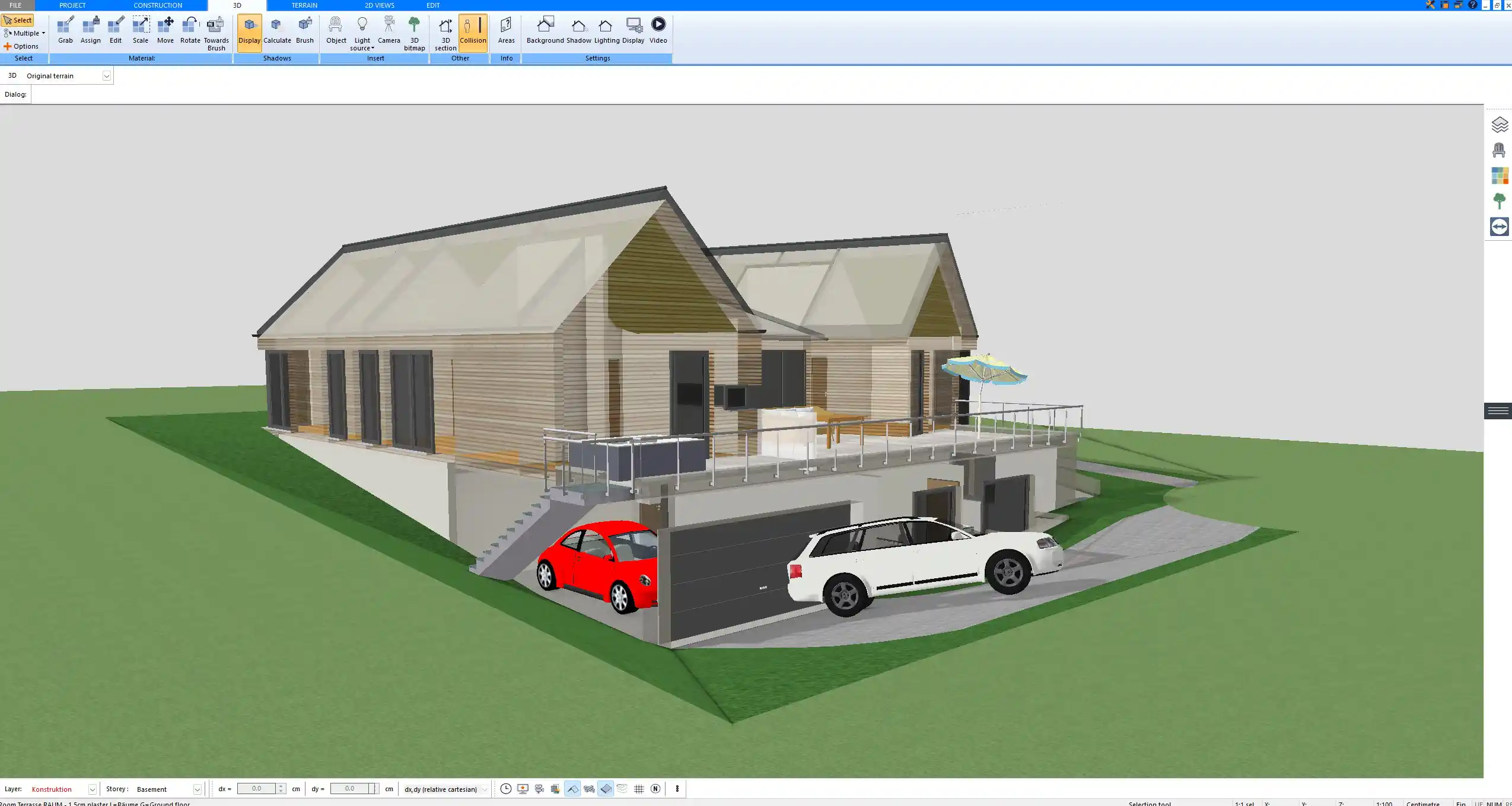
Elevations
Elevations are exterior views of the building. They should show:
-
All sides of the building
-
Exterior finishes and materials
-
Roof slopes and wall heights
-
Window and door arrangements
Elevations provide an accurate picture of how the building will appear from the outside.
Sections and Details
Sections cut vertically through the structure to reveal hidden components. They should indicate floor levels, ceiling heights, foundation depth, and roof structure. Details provide enlarged views of specific elements, such as:
-
Window and door connections
-
Staircase construction
-
Roof-to-wall junctions
-
Insulation and waterproofing layers
These drawings eliminate ambiguity and reduce errors during construction.
Structural Drawings
Structural drawings provide the backbone of the project. They include:
-
Foundation layout with reinforcement details
-
Framing plans for floors, walls, and roofs
-
Specifications for beams, columns, and load-bearing elements
These drawings must be precise to ensure stability and safety.
MEP (Mechanical, Electrical, Plumbing)
MEP drawings coordinate essential building systems:
-
HVAC layout with ducts and vents
-
Electrical circuits, lighting fixtures, and power outlets
-
Plumbing lines for water supply and drainage
Without detailed MEP plans, on-site clashes and delays are common.
Schedules and Legends
Schedules provide an overview of all repetitive elements in the building:
-
Door schedule with types, dimensions, and materials
-
Window schedule listing sizes and glazing
-
Finish schedule showing floor, wall, and ceiling finishes
Legends explain the symbols and abbreviations used across all drawings, ensuring consistency.
Common Mistakes to Avoid
-
Missing or unclear dimensions that make construction difficult
-
Inconsistent scales between different drawings
-
Overcrowded layouts with too much information on one sheet
-
Drawings that lack revision notes, leading to confusion on-site
Tips for Using Software to Create a Checklist
Modern CAD and 3D design programs simplify the process of preparing construction drawings. With Plan7Architect, you can:
-
Use templates to include all checklist items automatically
-
Switch between European metric units and U.S. imperial units, depending on project requirements
-
Organize drawings into layers for structural, MEP, and design components
-
Generate both 2D technical plans and 3D visualizations to better communicate with contractors and clients
Professional Construction Drawings with Plan7Architect
With Plan7Architect, you can create professional floor plans and complete construction drawings that include site plans, elevations, sections, details, and even full MEP layouts. The software allows you to switch easily between European and U.S. measurement systems, making it suitable for projects worldwide. Everything you have seen in this checklist can be planned and organized directly within the program. If you are looking for an efficient tool to prepare detailed construction drawings yourself, Plan7Architect offers the right balance between ease of use and professional features. Customers benefit from a 14-day cancellation policy, which replaces the need for a trial version and allows you to cancel your purchase quickly and simply by email.
Plan your project with Plan7Architect

Plan7Architect Pro 5 for $109.99
You don’t need any prior experience because the software has been specifically designed for beginners. The planning process is carried out in 5 simple steps:
1. Draw Walls

2. Windows & Doors

3. Floors & Roof

4. Textures & 3D Objects

5. Plan for the Building Permit

6. Export the Floor Plan as a 3D Model for Twinmotion

- – Compliant with international construction standards
- – Usable on 3 PCs simultaneously
- – Option for consultation with an architect
- – Comprehensive user manual
- – Regular updates
- – Video tutorials
- – Millions of 3D objects available
Why Thousands of Builders Prefer Plan7Architect
Why choose Plan7Architect over other home design tools?