When looking at construction drawings, you will encounter a standardized system of line types. These lines are not decorative; they carry meaning and define how builders, engineers, and architects communicate. The main line types are:
-
Continuous thick line
-
Continuous thin line
-
Dashed line
-
Chain thin line (center line)
-
Chain thick line
-
Dotted line
-
Break lines (short zigzag or long with zigzag)
-
Phantom line (dash-dot-dot pattern)
Continuous Thick Line
The continuous thick line is used for all visible outlines and edges of the building or structure. You will see it marking walls, doors, and main components that are visible in the view. Its strength and thickness make it stand out as the most important line type on the drawing.
Continuous Thin Line
The continuous thin line is reserved for dimensions, projection lines, leader lines, hatching, and short centerlines. In practice, these lines guide you through the drawing without distracting from the main elements. When I prepare drawings, I rely on thin lines to place measurements accurately, ensuring that every builder on site can read them clearly.
Dashed Line
Dashed lines indicate hidden edges or elements that are not visible in the view being presented. For example, beams behind walls, foundation parts below ground, or roof edges covered by another surface. Recognizing these lines prevents misunderstandings and mistakes during construction.
Chain Thin Line (Center Line)
The chain thin line, also called the center line, uses a dash-dot pattern. It marks symmetry axes, centers of walls or windows, and paths of rotation for doors. Whenever you are aligning structural components, these lines provide orientation.
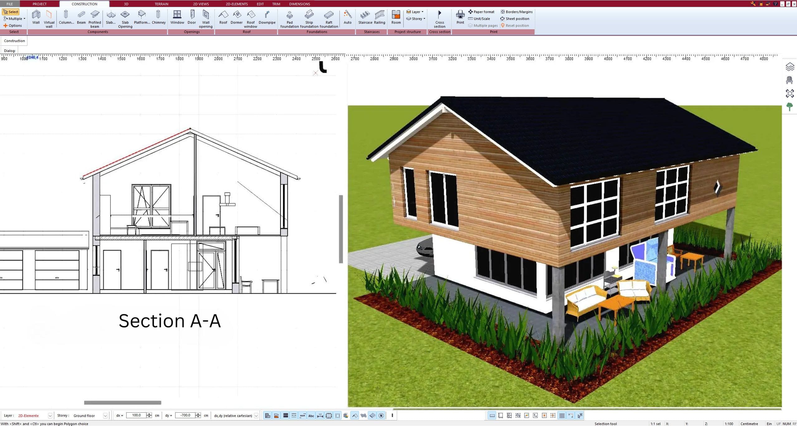
Chain Thick Line
Chain thick lines are bold versions of dash-dot lines. They are typically used to indicate cutting planes in section drawings. When you look at a section view of a building, these lines tell you exactly where the drawing was “cut” to show the interior details.
Dotted Line
Dotted lines are less common but can be used to show boundary limits, movement paths, or references for future construction. In some standards, dotted lines also represent secondary elements or provisional items.
Break Lines
Break lines, which can be short zigzags or long straight lines with a zigzag break, show that part of the object has been omitted. This is useful when the full length of a wall, staircase, or beam does not fit on the page, but you still want to present the detail clearly.
Phantom Line
Phantom lines, often drawn with a dash-dot-dot pattern, indicate alternative positions, repeated details, or adjacent parts. They are valuable when you need to show possible placements of an element, such as a door swing in multiple positions.
Line Types and Their Functions in Construction Drawings
The following table provides an overview of line types, their appearance, and function:
| Line Type | Appearance | Purpose in Drawing |
|---|---|---|
| Continuous Thick | Solid, bold | Visible outlines, walls, main structures |
| Continuous Thin | Solid, light | Dimensions, hatching, projection lines |
| Dashed | Short broken line | Hidden edges, elements not in view |
| Chain Thin | Dash-dot pattern | Center lines, axes, symmetry |
| Chain Thick | Dash-dot, bold | Cutting planes for sections |
| Break Line | Zigzag or wave | Omitted parts, shortened details |
| Phantom Line | Dash-dot-dot pattern | Alternative positions, repeated parts |
Why Different Line Types Matter
Each line type is part of an international language of construction. Builders on site must be able to understand a drawing quickly and without errors. Using the correct line types ensures clarity and consistency. Misinterpretations caused by incorrect line usage can lead to costly mistakes. For this reason, drawings are prepared following strict line-type conventions.
Standards and Variations
Line types are defined by international standards such as ISO and DIN in Europe, and ANSI in the United States. Although the graphic symbols may vary slightly, the meanings remain similar. When working internationally, you may encounter different drafting habits, but the principles remain universal. Professional design software like Plan7Architect allows you to set up your projects with both metric (meters, millimeters) and imperial (feet, inches) units, which ensures flexibility no matter where you are based.
Tips for Reading and Creating Construction Drawings
-
Always check the legend on a drawing for line type definitions, especially if you are working with international teams.
-
Use consistent line weights and styles across your project.
-
Organize your drawing layers in CAD or 3D software so that line types remain uniform.
-
Practice recognizing hidden lines and center lines quickly; this skill makes reading complex plans much easier.
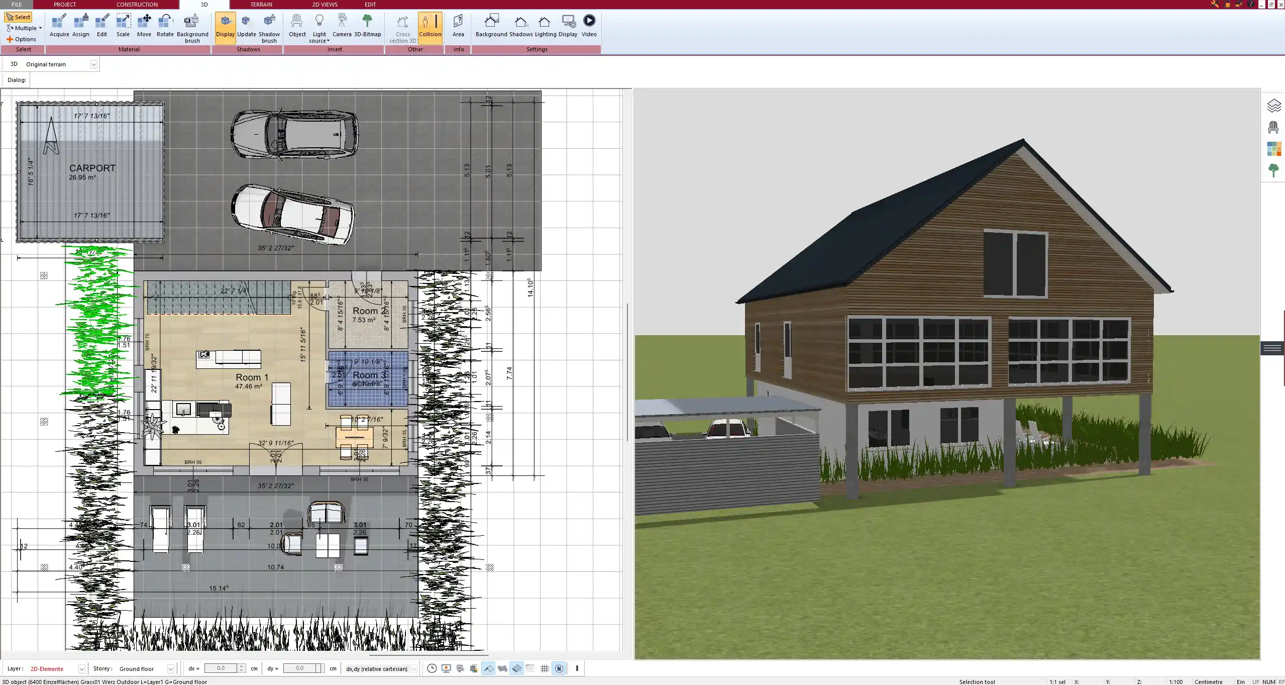
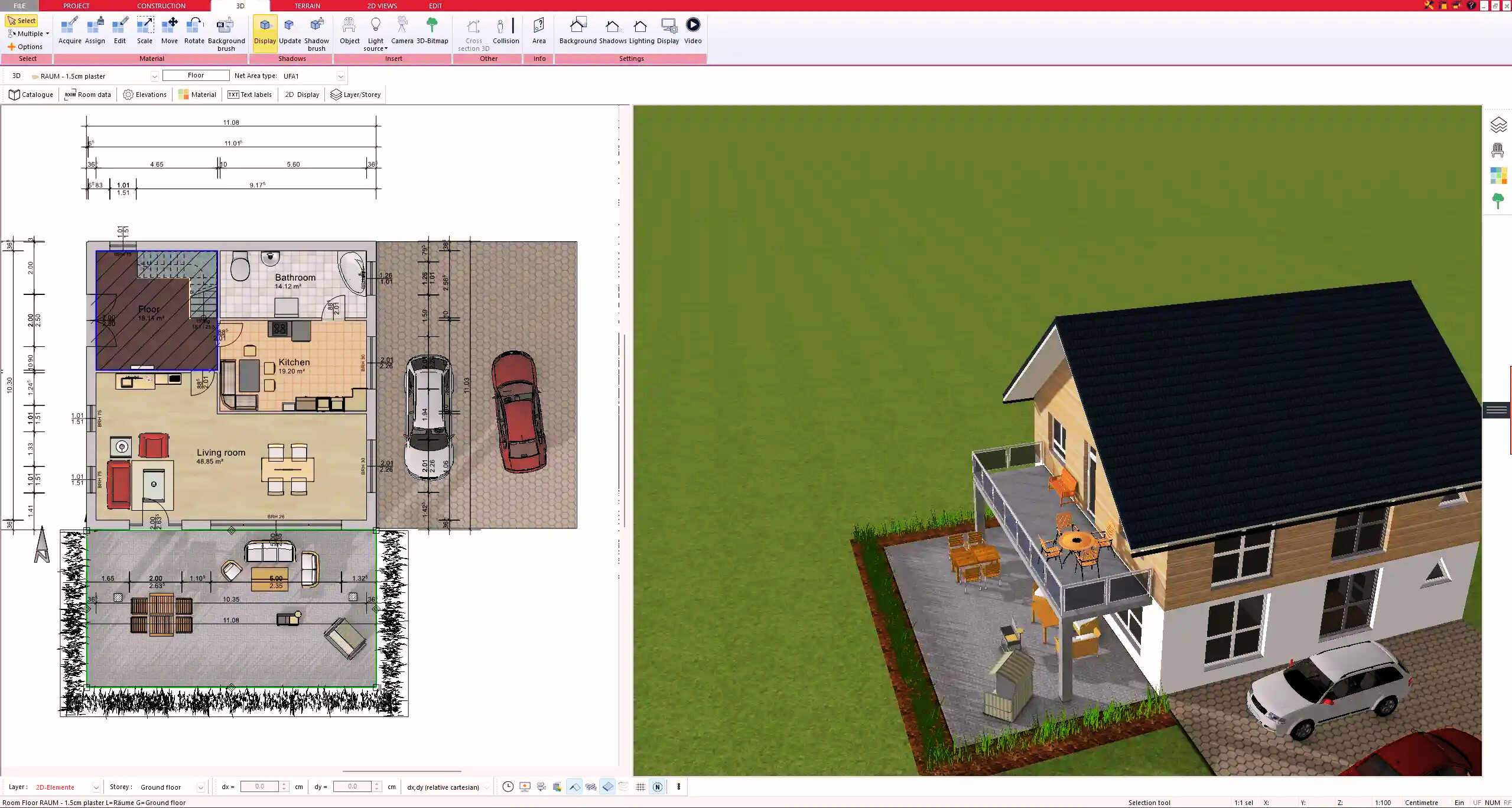
Create Professional Construction Drawings with Plan7Architect
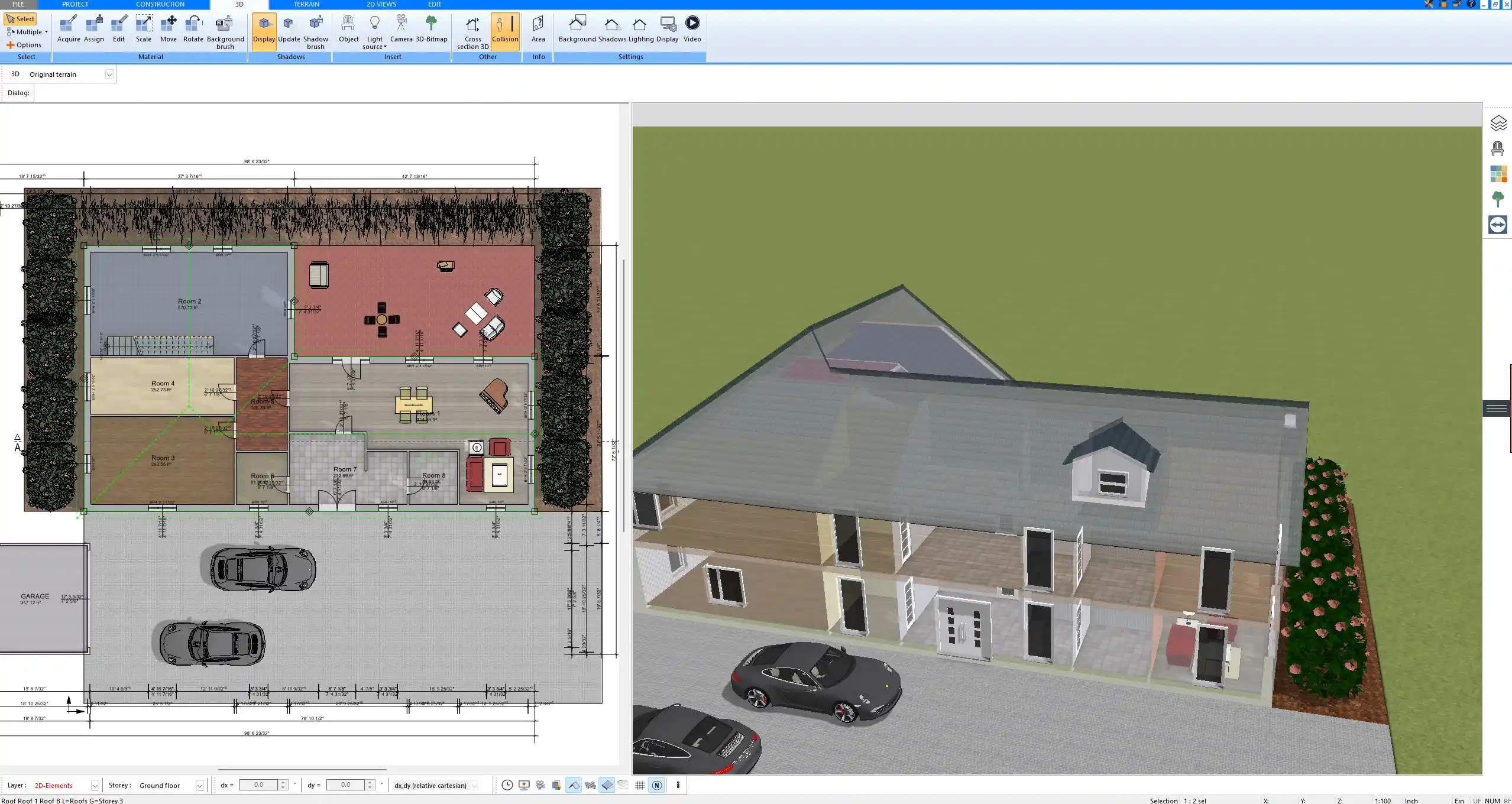
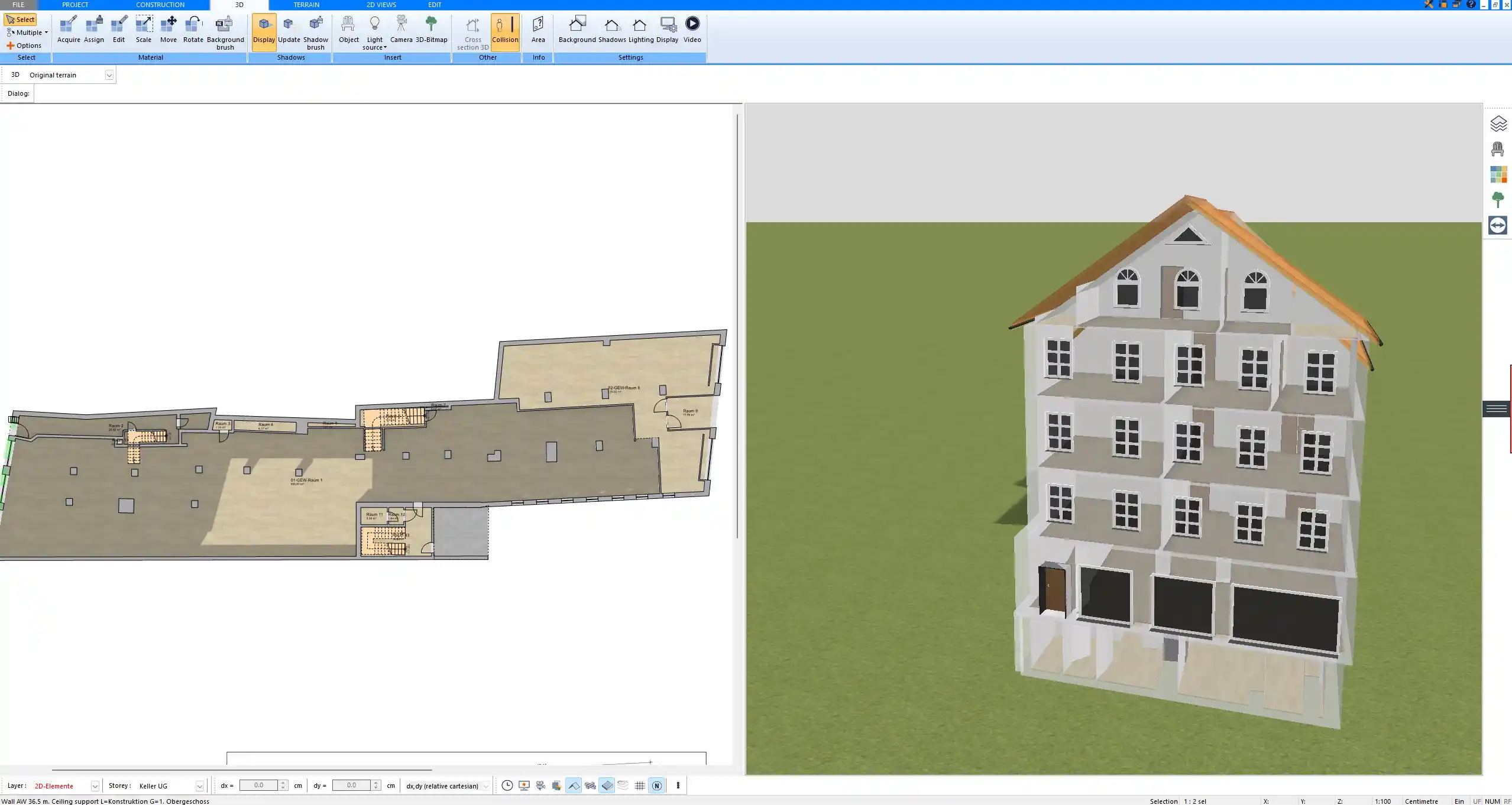
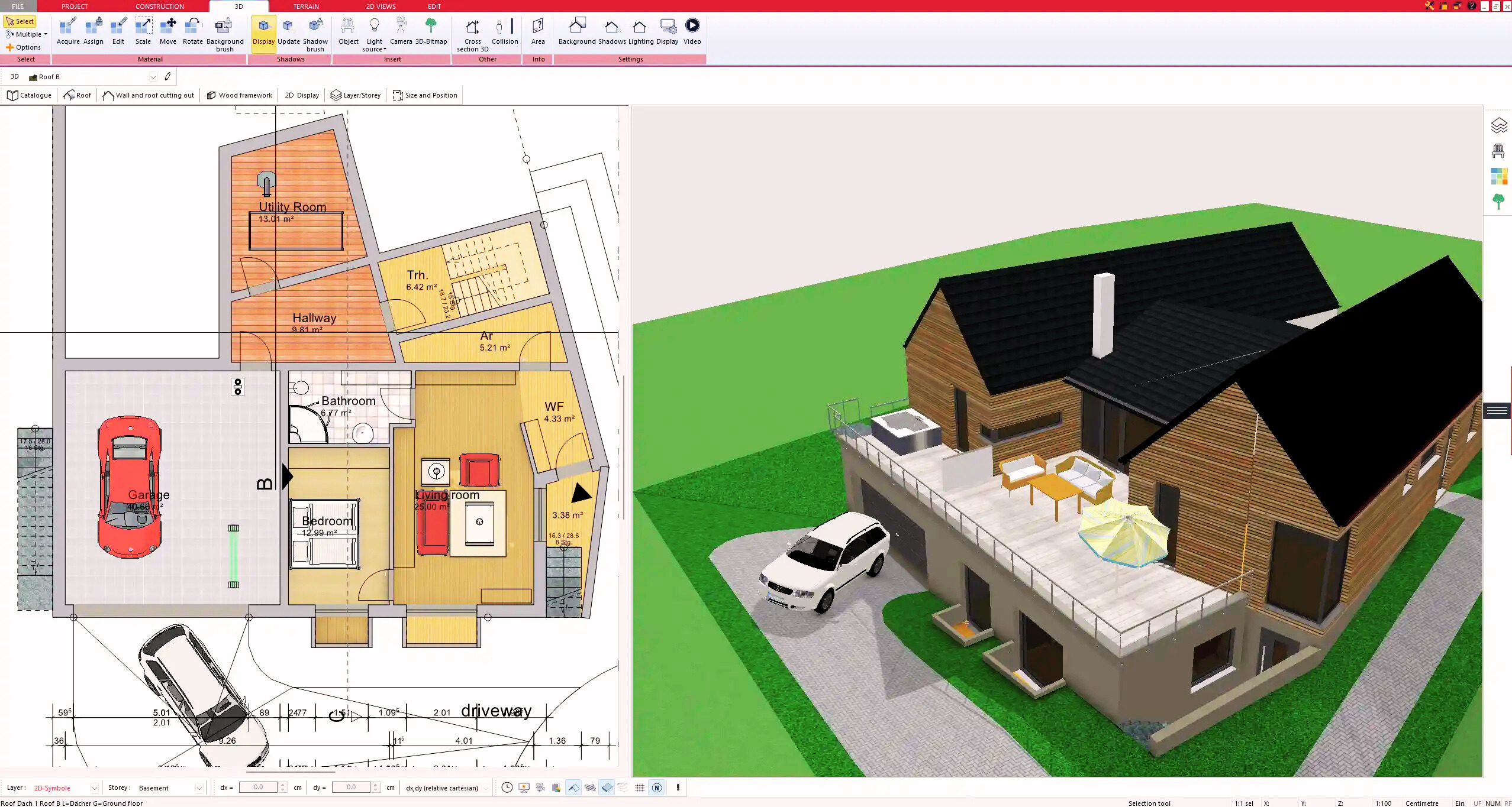
With Plan7Architect you can create professional construction drawings and apply the correct line types directly in your project. Whether you are designing floor plans, section views, or detailed layouts, the software provides tools to represent all standard line types clearly. You can work with both European and American units, switching between meters and millimeters or feet and inches depending on your needs. This flexibility makes your planning process smooth and precise. As a customer, you benefit from a 14-day cancellation right, so you can cancel your purchase easily by email if needed. This replaces the idea of a trial version and allows you to test the software without risk. If you want to prepare professional drawings yourself, Plan7Architect is the right tool for you.
Plan your project with Plan7Architect
Plan7Architect Pro 5 for $169.99
You don’t need any prior experience because the software has been specifically designed for beginners. The planning process is carried out in 5 simple steps:
1. Draw Walls
2. Windows & Doors
3. Floors & Roof
4. Textures & 3D Objects
5. Plan for the Building Permit
6. Export the Floor Plan as a 3D Model for Twinmotion
- – Compliant with international construction standards
- – Usable on 3 PCs simultaneously
- – Option for consultation with an architect
- – Comprehensive user manual
- – Regular updates
- – Video tutorials
- – Millions of 3D objects available
Why Thousands of Builders Prefer Plan7Architect
Why choose Plan7Architect over other home design tools?