Symbols in construction drawings are standardized graphical representations used to describe building elements, fixtures, materials, and systems. Instead of writing long descriptions, architects and engineers use these symbols as a universal language that can be understood by builders, contractors, and inspectors across the world. They allow complex information to be shown in a compact, clear way.
You will see symbols for walls, doors, windows, electrical outlets, plumbing fixtures, and even heating or air conditioning systems. Without them, construction drawings would be almost impossible to read efficiently.
Why Symbols Are Important
Construction drawings contain a large amount of detailed information. Using symbols ensures that everyone involved in a project can read the same plan without misunderstandings.
Main reasons why symbols are important:
-
They save space on drawings and make them easier to read.
-
They provide clarity and accuracy in communication.
-
They create a shared language across different trades.
-
They are recognized internationally, which is essential for global projects.
-
They have legal and safety relevance, because unclear plans could lead to dangerous mistakes on site.
Common Categories of Construction Drawing Symbols
Architectural Symbols
Architectural symbols show the structural and design elements of a building. These are usually the first symbols you encounter when reading a floor plan.
Examples include:
-
Walls: shown with solid parallel lines, sometimes with hatch patterns to indicate material.
-
Doors: drawn with arcs to indicate swing direction.
-
Windows: displayed with simple breaks in wall lines or more detailed window type symbols.
-
Stairs: represented with lines and arrows indicating direction.
-
Furniture: used to show scale and layout of rooms.
-
Dimension lines: mark exact measurements and distances.
Electrical Symbols
Electrical drawings contain many specialized symbols that show power and low-voltage systems.
Typical electrical symbols:
-
Outlets: small circles or rectangles, sometimes marked for type (standard, high-voltage, data).
-
Switches: shown as “S” with variations for single-pole, three-way, or dimmer.
-
Light fixtures: represented by circles, squares, or special shapes depending on the type.
-
Ceiling fans: symbolized by a small circle with curved blades.
-
Distribution panels: rectangles or boxes with internal details.
Plumbing Symbols
Plumbing systems also rely heavily on symbols to indicate fixtures and pipe networks.
Common plumbing symbols:
-
Sinks: shown as simple squares or rectangles with faucet marks.
-
Toilets: often represented with oval or rectangle symbols.
-
Showers and bathtubs: depicted with outlines of the fixture.
-
Hot and cold water lines: indicated with dashed or solid lines, sometimes labeled.
-
Valves and pumps: represented with geometric shapes like triangles or diamonds.
HVAC Symbols
Heating, ventilation, and air conditioning systems need special symbols to show air circulation.
Typical HVAC symbols:
-
Air ducts: represented by lines, often with cross-hatching.
-
Vents and diffusers: small rectangles or squares with directional arrows.
-
Radiators or heating units: shown with patterns of parallel lines.
-
Thermostats: a small circle with “T” or similar identification.
Structural Symbols
Structural drawings use symbols to represent load-bearing elements and reinforcements.
Common structural symbols:
-
Foundations: usually shown as thick lines or hatch patterns.
-
Beams: solid lines with designations for material and size.
-
Columns: circles or rectangles depending on material type.
-
Reinforcement: hatch marks or diagonal patterns for steel bars or concrete slabs.
How to Read Construction Symbols
Every professional drawing includes a legend or key. This is where all the symbols used in the plan are explained. Before working with a drawing, always check the legend first.
Keep in mind that variations exist depending on the country or region. Some details differ between European and American plans. Modern design software such as Plan7Architect allows you to switch between European and American measurement systems, so you can work according to the standards you need.
To become confident in reading symbols, practice with real examples and compare them to the legend. With time, you will recognize symbols automatically.
Standardization of Symbols
Symbols are standardized to ensure consistency across projects and countries.
-
ISO standards are widely used in Europe and internationally.
-
ANSI standards are commonly followed in the United States.
-
Local building authorities may add regional requirements.
These standards make it possible for professionals from different backgrounds to collaborate effectively on the same project.
Tips for Working With Construction Symbols
-
Always begin by reading the legend on the plan.
-
Do not assume that symbols are the same everywhere; confirm the standard used.
-
Use software that provides preloaded symbol libraries, such as Plan7Architect, to avoid mistakes.
-
If you are preparing your own drawings, keep your symbols consistent across the entire plan.
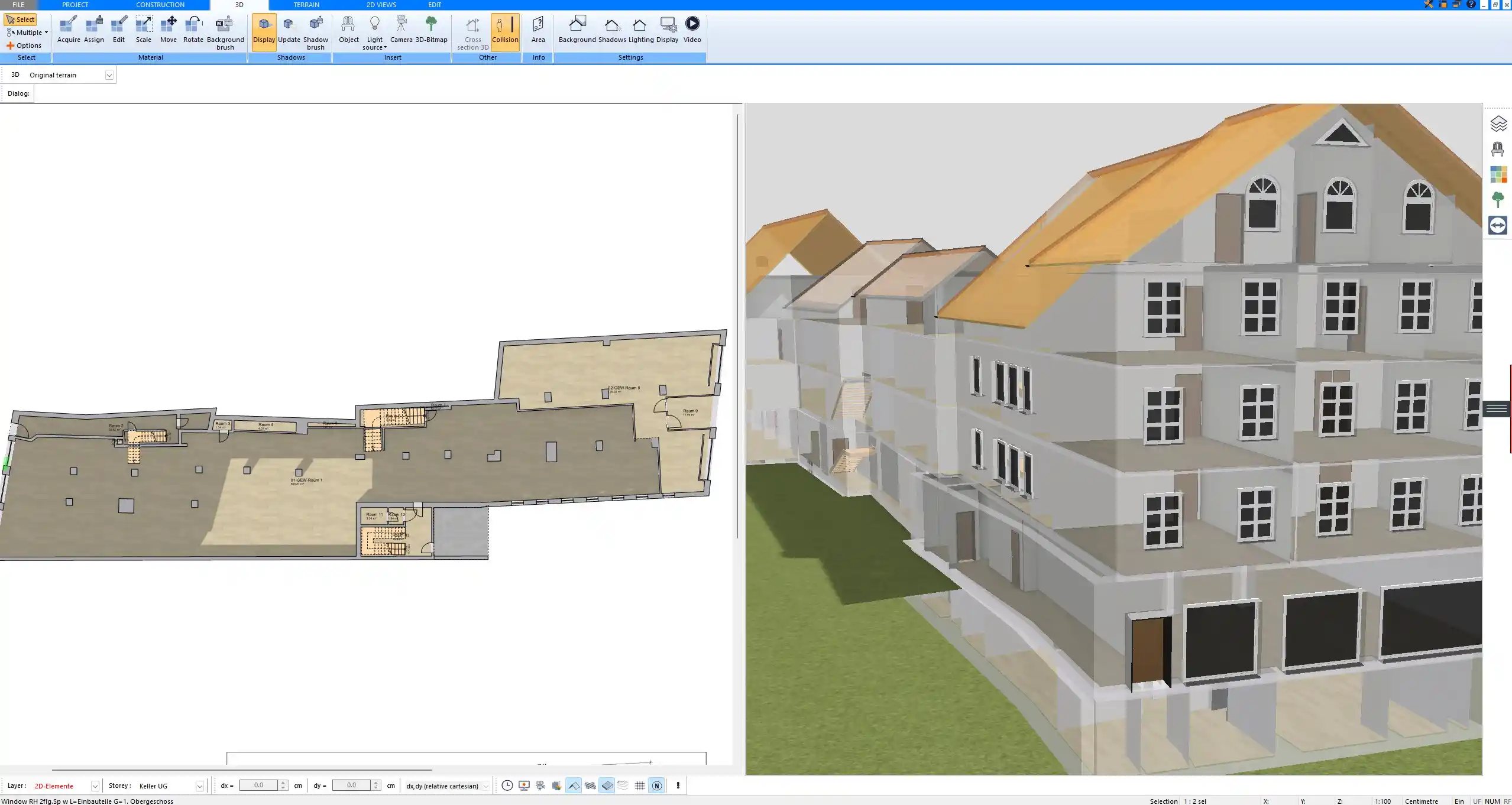
Table of Common Construction Symbols
| Category | Symbol Example (simplified) | Meaning | Notes |
|---|---|---|---|
| Architectural | ⎔ | Window | Variations show window types |
| Electrical | ○ | Light outlet | Styles may differ between Europe and U.S. |
| Plumbing | WC | Toilet | Standardized almost everywhere |
| HVAC | ▭ | Air vent | Size specified in notes |
| Structural | ▓ | Reinforced concrete area | Often paired with dimensions |
Software and Digital Tools for Symbols
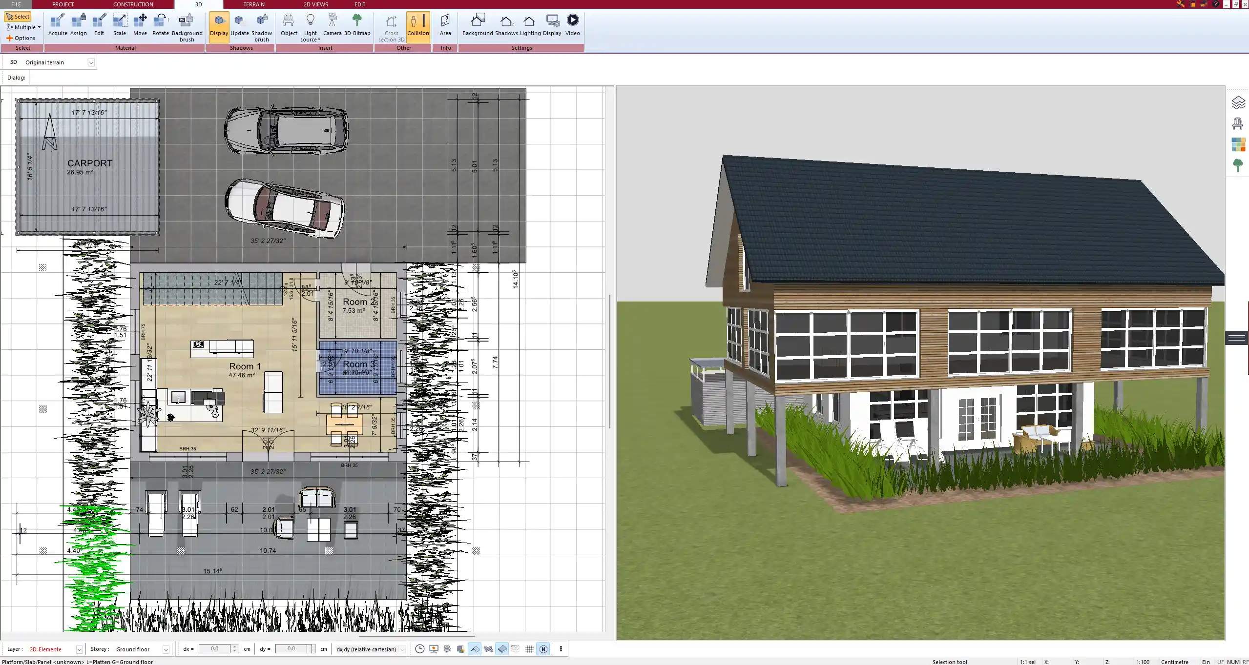
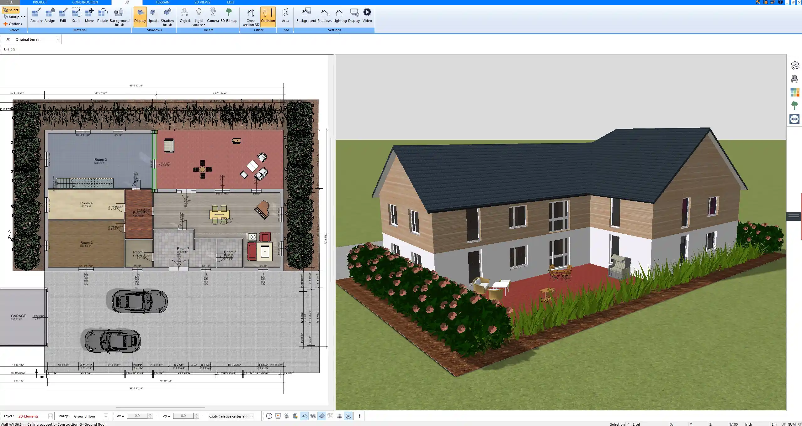
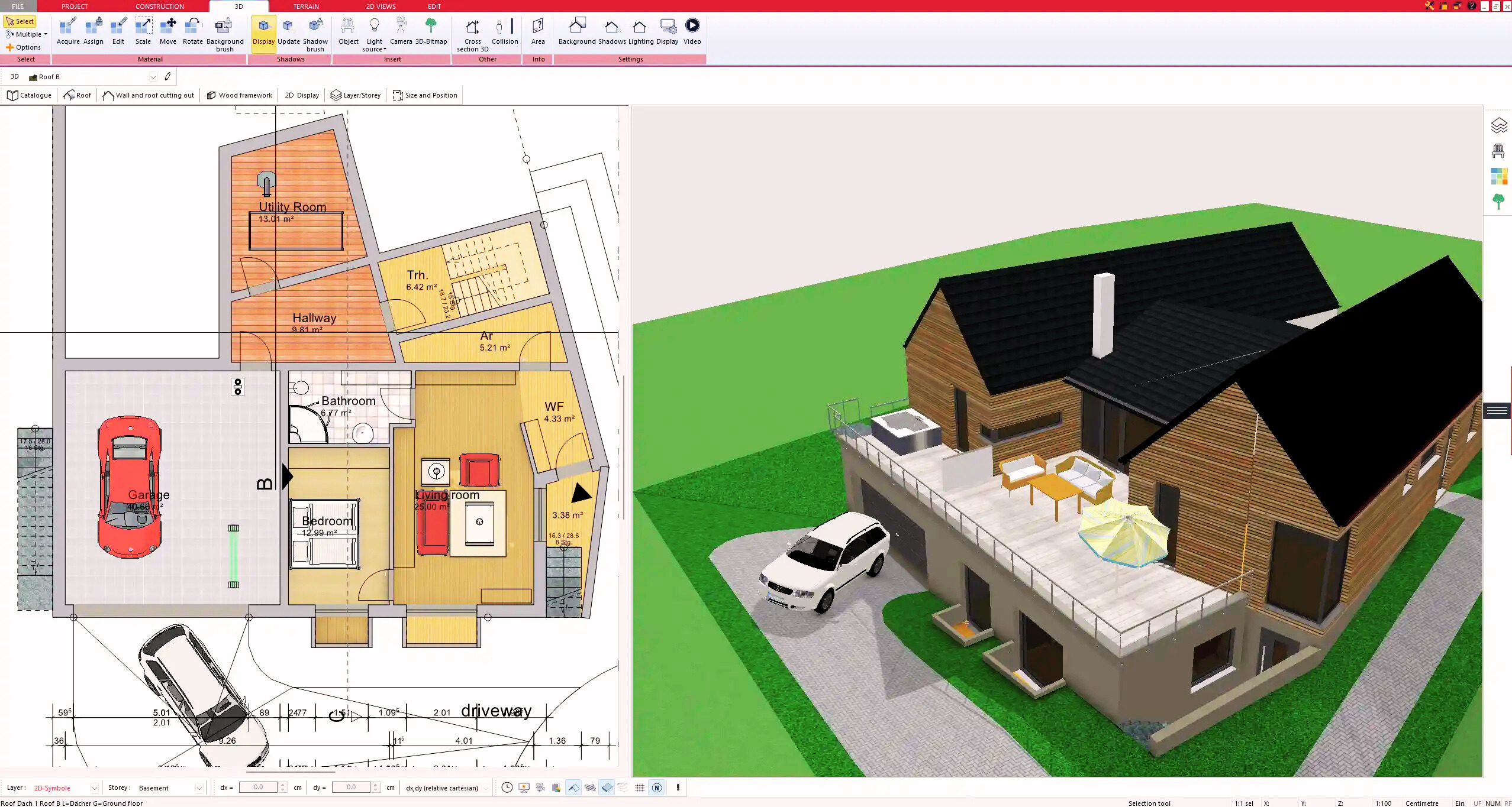
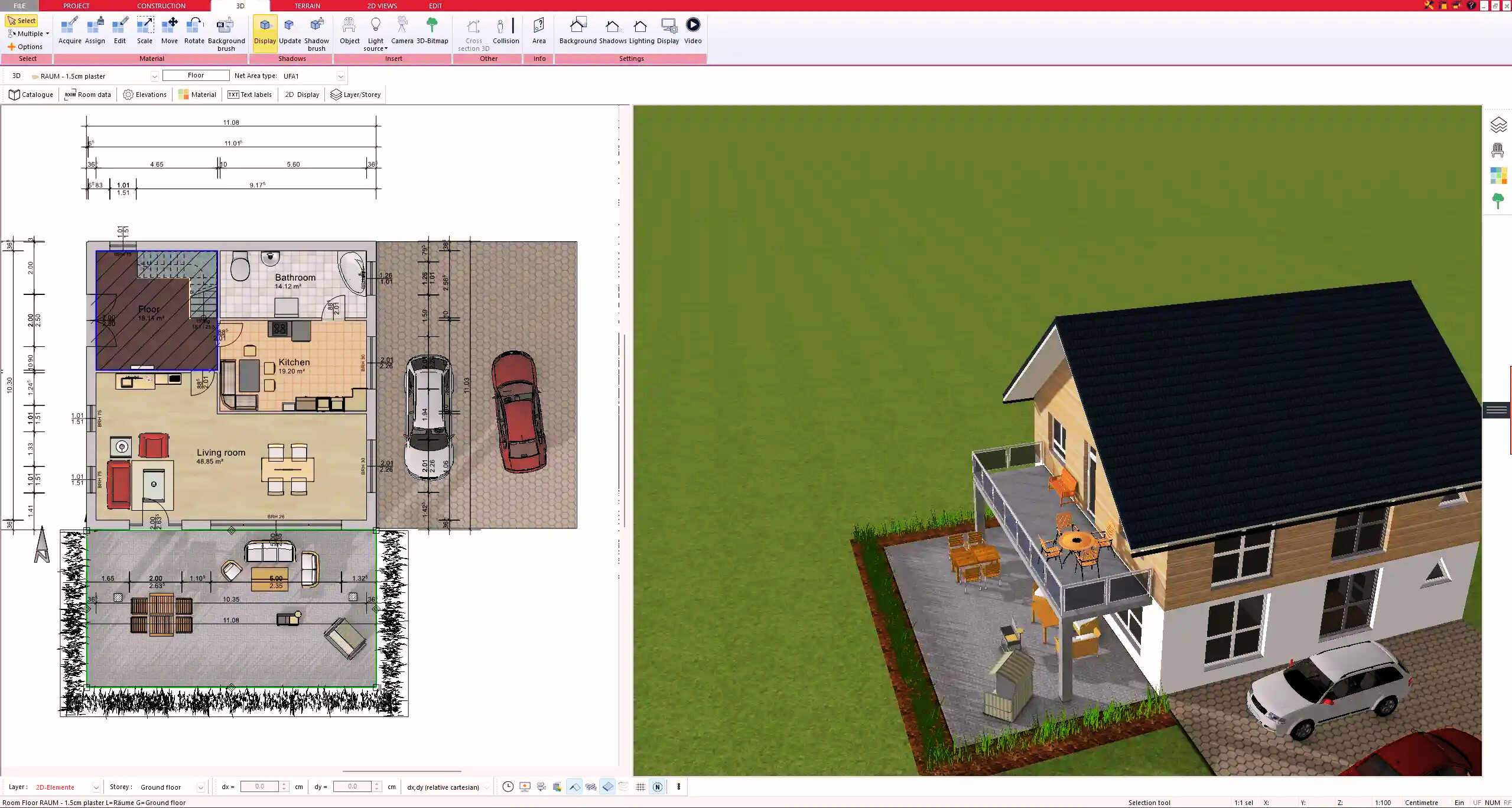
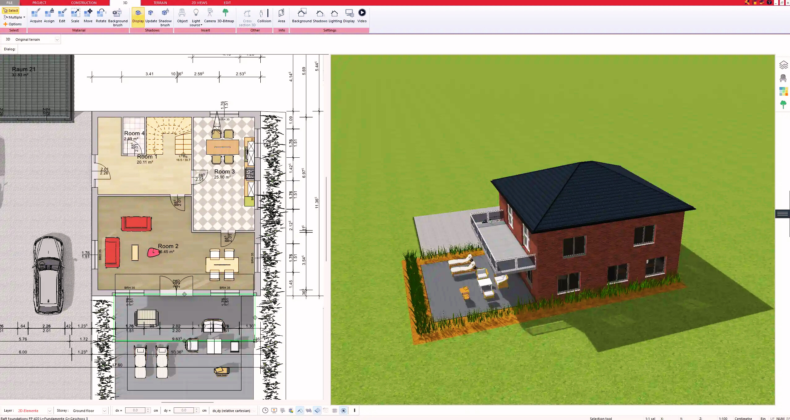
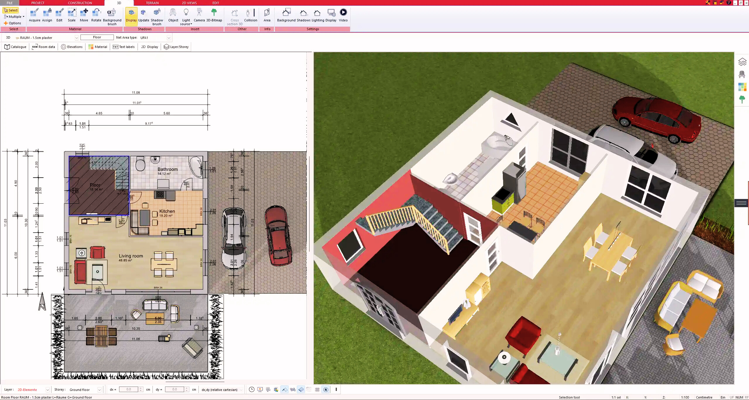
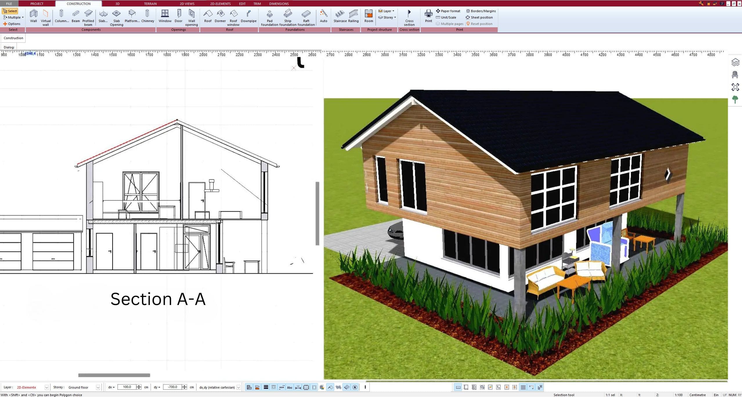
Modern CAD and BIM programs include symbol libraries that help you draw correctly without memorizing every detail. Plan7Architect is one example of such software, offering extensive symbol collections for architecture, plumbing, HVAC, and electrical layouts. You can place symbols directly into your 2D plan and then instantly view them in 3D. This ensures accuracy and saves time compared to manual drafting.
Create Professional Floor Plans with Plan7Architect
With Plan7Architect, you can create professional construction drawings that include all the necessary symbols for architecture, electrical, plumbing, HVAC, and structural planning. The software allows you to switch between European and American measurement units, so you can design according to your local standards. You can plan doors, windows, furniture, pipes, outlets, or heating systems directly in 2D and visualize them instantly in 3D. If you purchase Plan7Architect, you benefit from a 14-day right of withdrawal and can easily cancel your purchase via email if needed. This replaces the traditional trial version and gives you full security when testing the software. If you want to create professional and detailed floor plans yourself, Plan7Architect is the right choice for you.
Plan your project with Plan7Architect
Plan7Architect Pro 5 for $119.99
You don’t need any prior experience because the software has been specifically designed for beginners. The planning process is carried out in 5 simple steps:
1. Draw Walls
2. Windows & Doors
3. Floors & Roof
4. Textures & 3D Objects
5. Plan for the Building Permit
6. Export the Floor Plan as a 3D Model for Twinmotion

- – Compliant with international construction standards
- – Usable on 3 PCs simultaneously
- – Option for consultation with an architect
- – Comprehensive user manual
- – Regular updates
- – Video tutorials
- – Millions of 3D objects available
Why Thousands of Builders Prefer Plan7Architect
Why choose Plan7Architect over other home design tools?