Mechanical drawings are used in construction plans whenever a building project requires precise details of technical systems that go beyond walls, roofs, and basic layouts. They are essential for heating, ventilation, and air conditioning (HVAC), plumbing, electrical wiring, and fire protection systems. You will find them in both residential and commercial projects, and they are particularly critical for larger or more complex buildings where many systems need to work together. These drawings are included during the design stage, the permitting process, and the actual construction, ensuring that builders and contractors know exactly how to install each system correctly.
What Mechanical Drawings Include
HVAC Layouts
HVAC drawings show how air flows through a building. They include the placement of ductwork, vents, fans, and equipment like furnaces or air handling units. They also define the size of ducts and equipment, making sure that every room receives proper heating or cooling.
Plumbing Plans
Plumbing drawings detail the network of pipes, water lines, and fixtures. They show hot and cold water supplies, drainage, vent lines, and connections for sinks, showers, toilets, and other appliances. In multi-story buildings, these plans also help to coordinate vertical shafts where pipes run between floors.
Electrical Schematics
Electrical drawings include wiring paths, outlets, lighting fixtures, switches, and control panels. They also define the placement of circuit breakers and distribution boards. Clear electrical drawings are vital to avoid conflicts with plumbing or HVAC layouts and to ensure that the system is safe and reliable.
Fire Safety and Other Systems
Mechanical drawings often include fire protection systems such as sprinklers, smoke detectors, and alarm wiring. In commercial buildings, additional mechanical equipment like elevators or specialized ventilation systems also appear in these drawings.
Why Mechanical Drawings Are Important
Mechanical drawings are important because they:
-
Ensure that architects, engineers, and contractors can coordinate their work without conflicts
-
Provide installers with accurate step-by-step information
-
Reduce errors and expensive on-site changes
-
Guarantee compliance with building safety regulations
-
Support future maintenance and upgrades by leaving a clear record of all systems
At What Stage of a Project They Are Used
Design Phase
During design, engineers use mechanical drawings to plan HVAC, plumbing, and electrical systems in harmony with the building’s structure and architecture.
Permitting Phase
Building authorities often require mechanical drawings before granting permits. These drawings prove that systems meet local codes and safety requirements.
Construction Phase
On the job site, contractors and tradespeople rely on mechanical drawings to know exactly where pipes, ducts, and wires should be installed.
Maintenance and Renovation
Mechanical drawings remain valuable after construction is complete. They are used as a reference during repairs, upgrades, or when extending a building, making it easier to locate hidden pipes, ducts, or wiring.
Residential vs. Commercial Use
In residential construction, mechanical drawings are usually simpler. A single-family home may combine HVAC, plumbing, and electrical details into fewer sheets, and sometimes they are included within the architectural drawings. In commercial or industrial construction, mechanical drawings are far more detailed and exist as separate sets. Complex systems, high-capacity HVAC equipment, and fire protection systems make them indispensable in large projects like office buildings, hospitals, or factories.
Tools and Software for Creating Mechanical Drawings
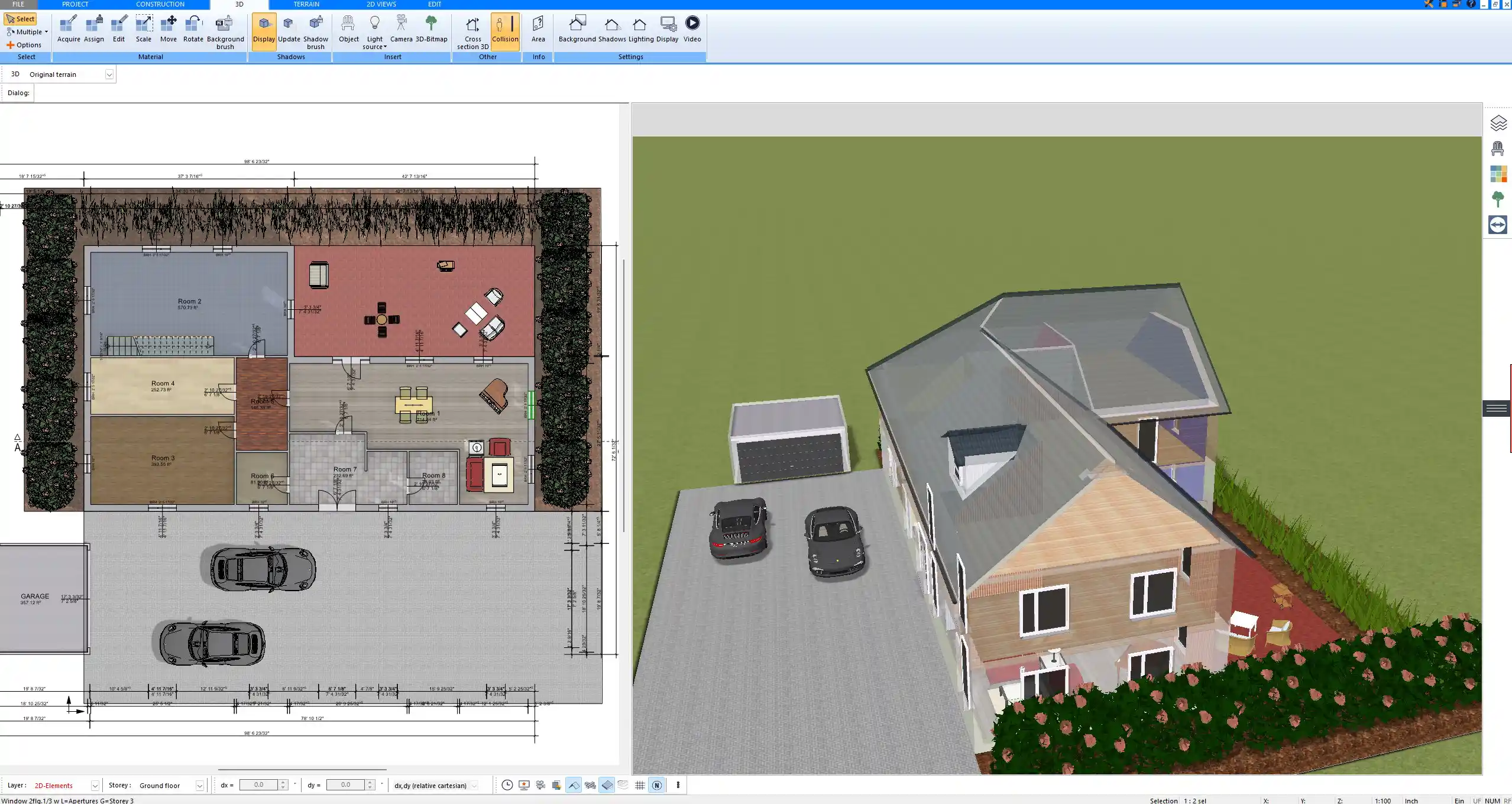
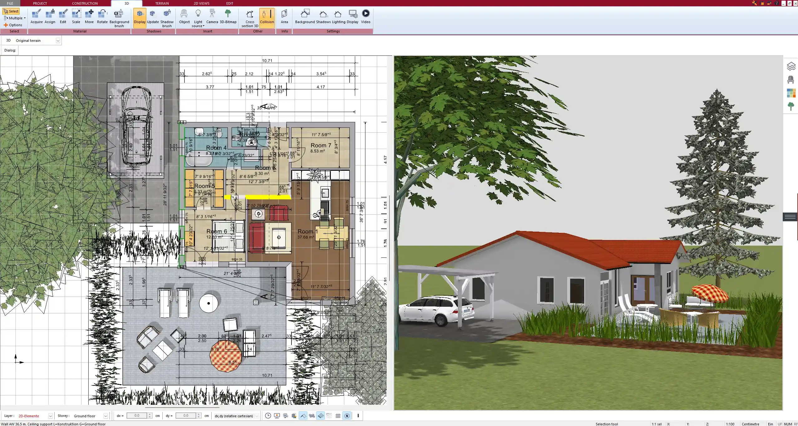
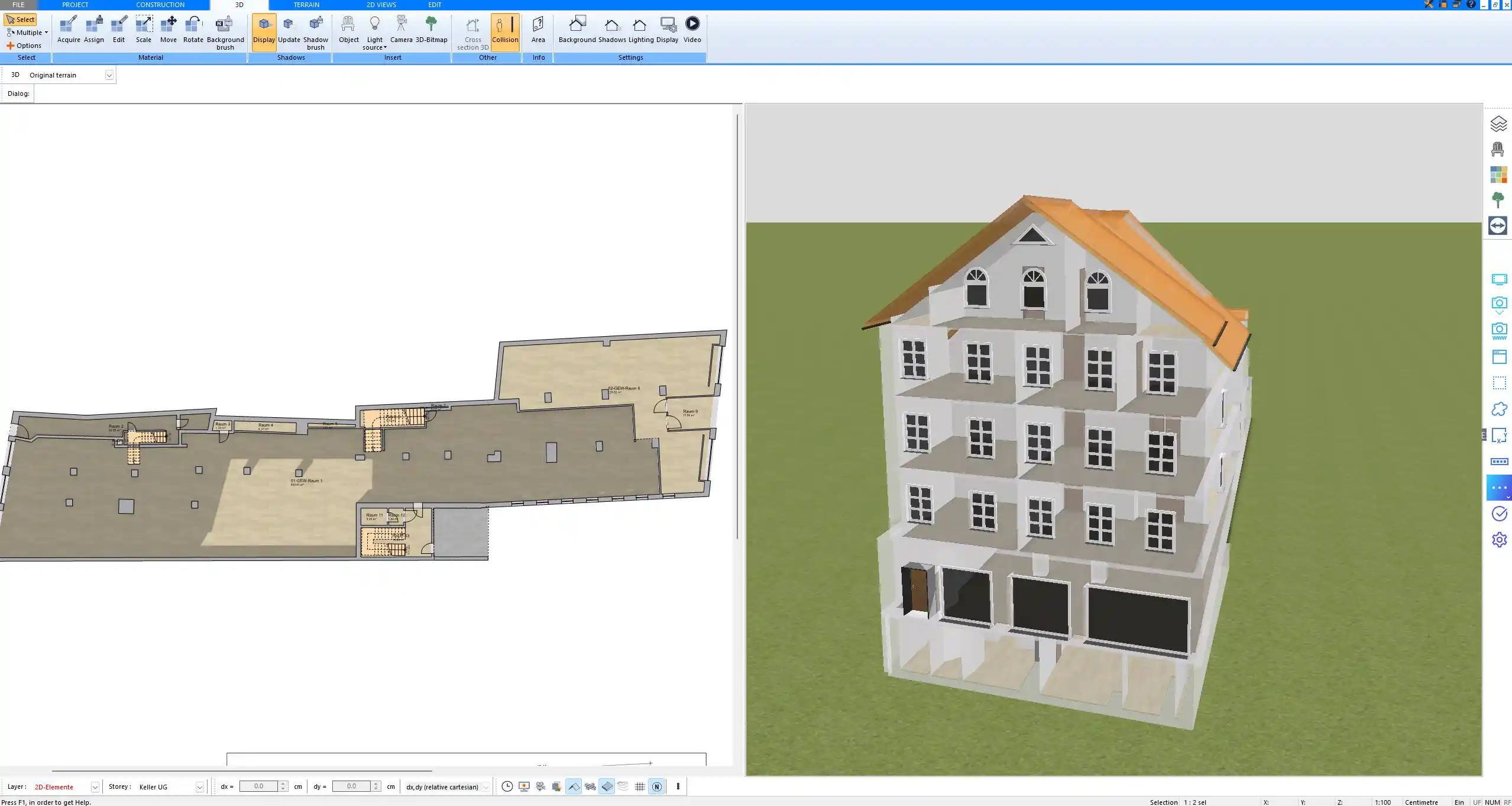
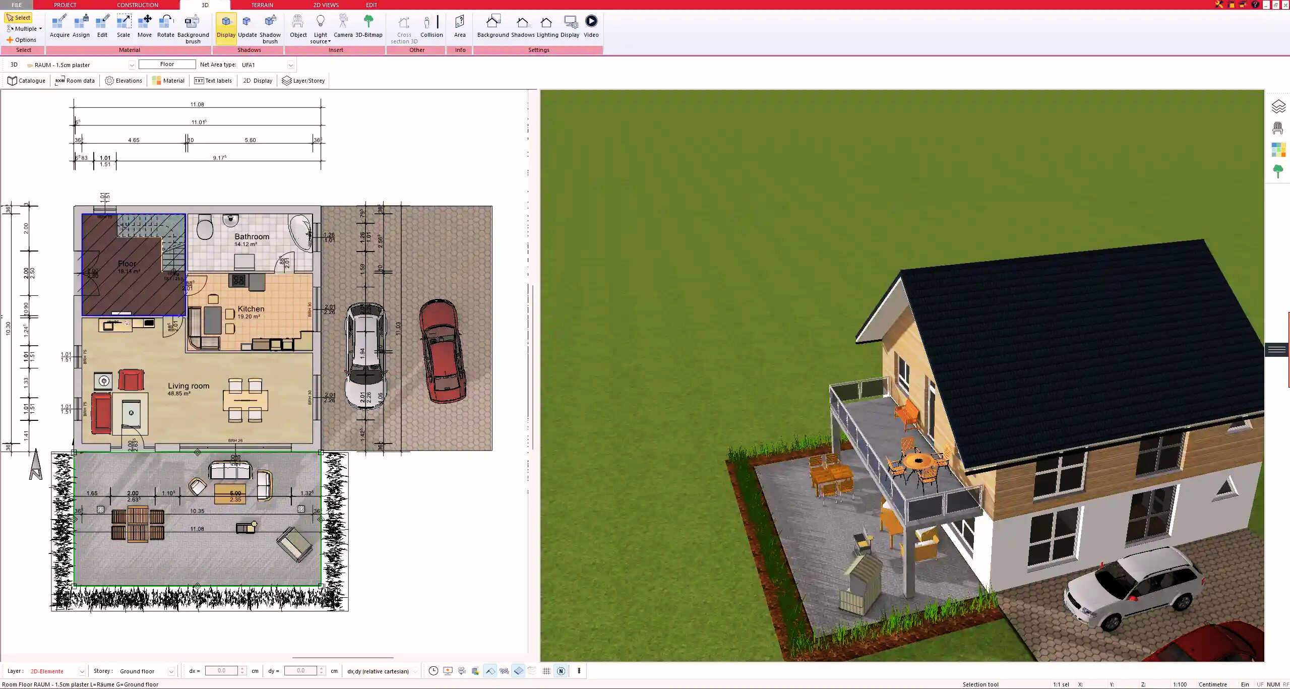
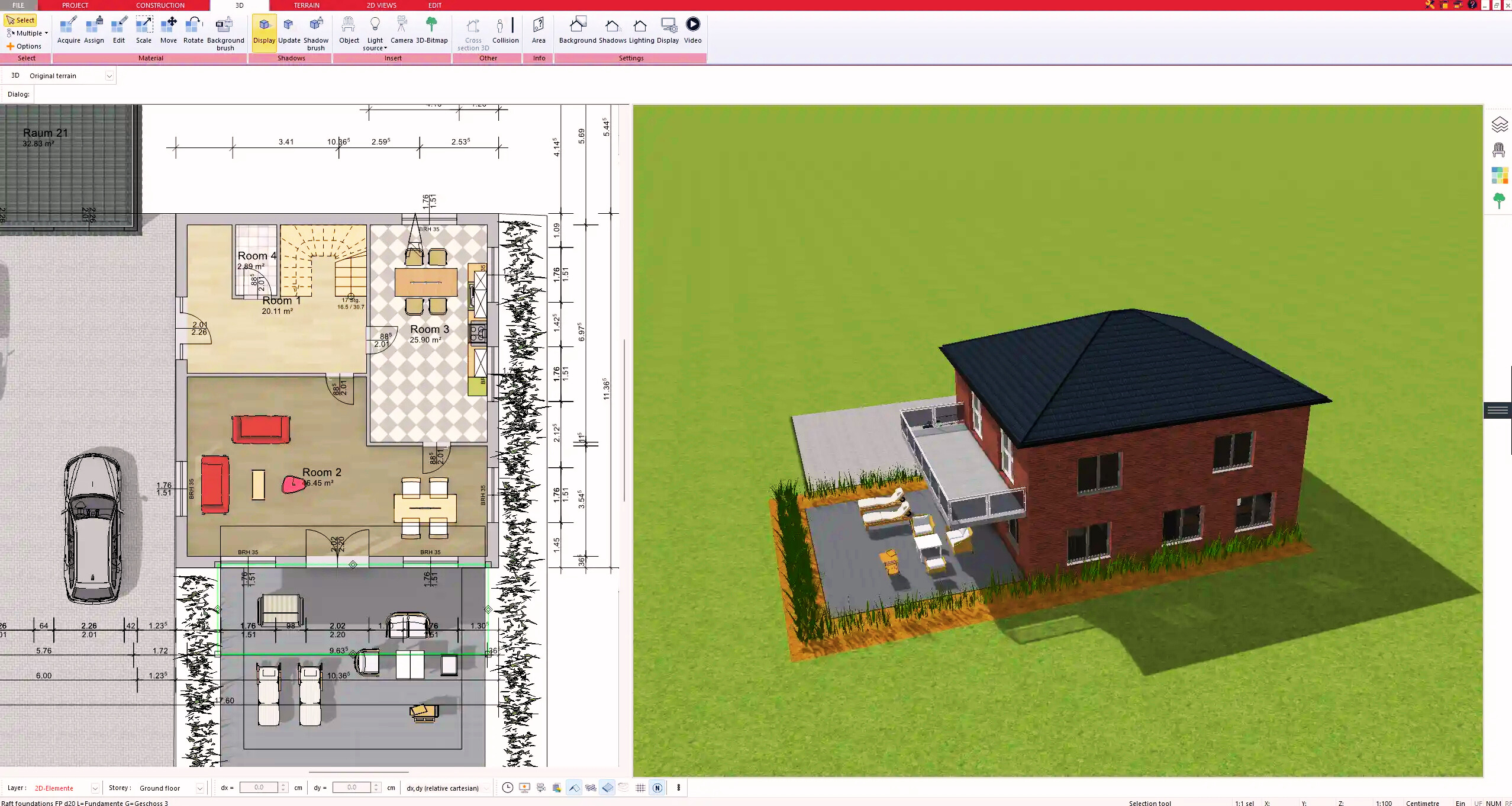
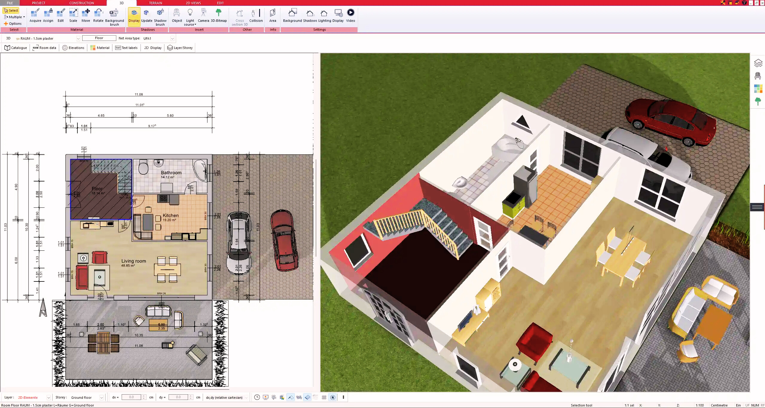
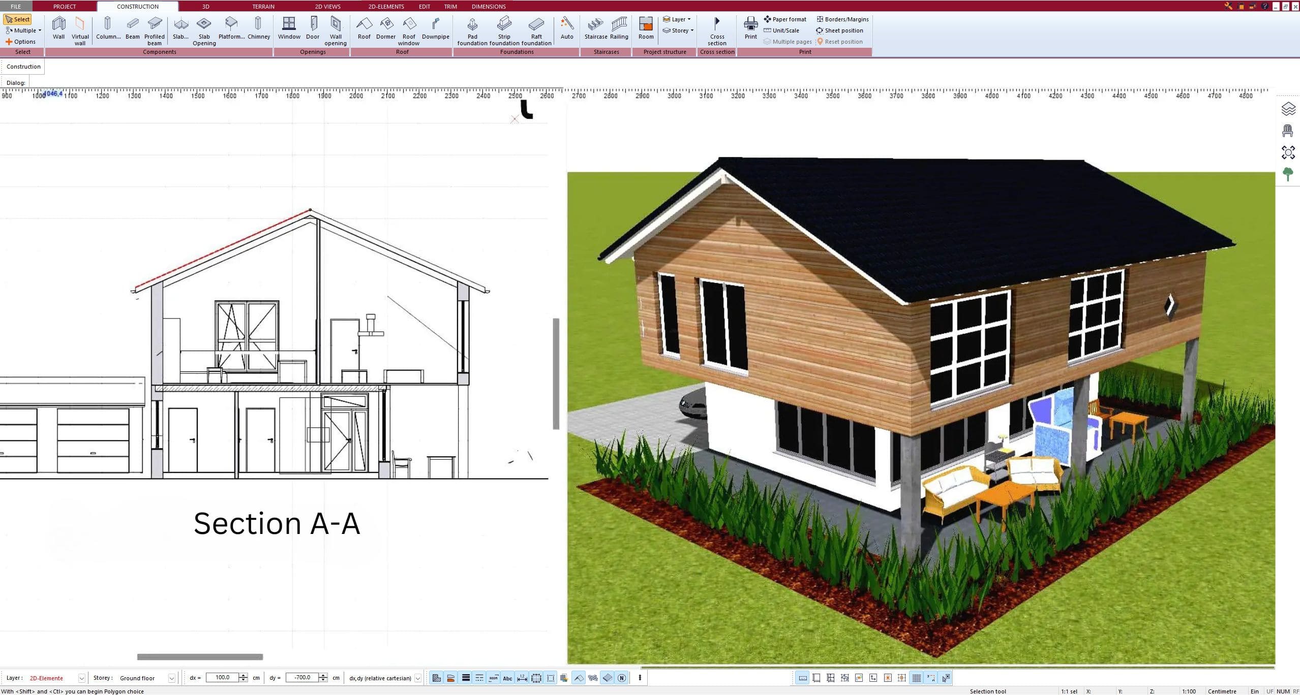
Mechanical drawings have traditionally been created with CAD software like AutoCAD or Revit. Today, specialized software such as Plan7Architect also makes it possible for private builders, professionals, and companies to design construction projects that include HVAC, plumbing, and electrical layouts. In Plan7Architect you can work in both metric units (meters, centimeters) and imperial units (feet, inches), making it suitable for projects in Europe, the United States, and other regions. The software lets you switch between 2D floor plans and 3D visualization, so you can immediately see how mechanical systems interact with the architecture.
Tips for Reading and Using Mechanical Drawings
-
Always check the legend and symbols for clarity.
-
Compare mechanical layouts with architectural and structural drawings to spot conflicts.
-
Verify the scale and whether metric or imperial units are used.
-
Use color-coded layers if available to separate plumbing, electrical, and HVAC.
Common Symbols and Conventions in Mechanical Drawings
| Symbol | Meaning |
|---|---|
| ● | Light fixture |
| ☐ | Electrical outlet |
| Δ | Switch |
| ——— | Duct line |
| ║ | Pipe line |
| ◎ | Sprinkler head |
| ◯ | Smoke detector |
These symbols may vary by region, but most professional drawings include a legend to explain them clearly.
Plan Professional Construction Drawings with Plan7Architect
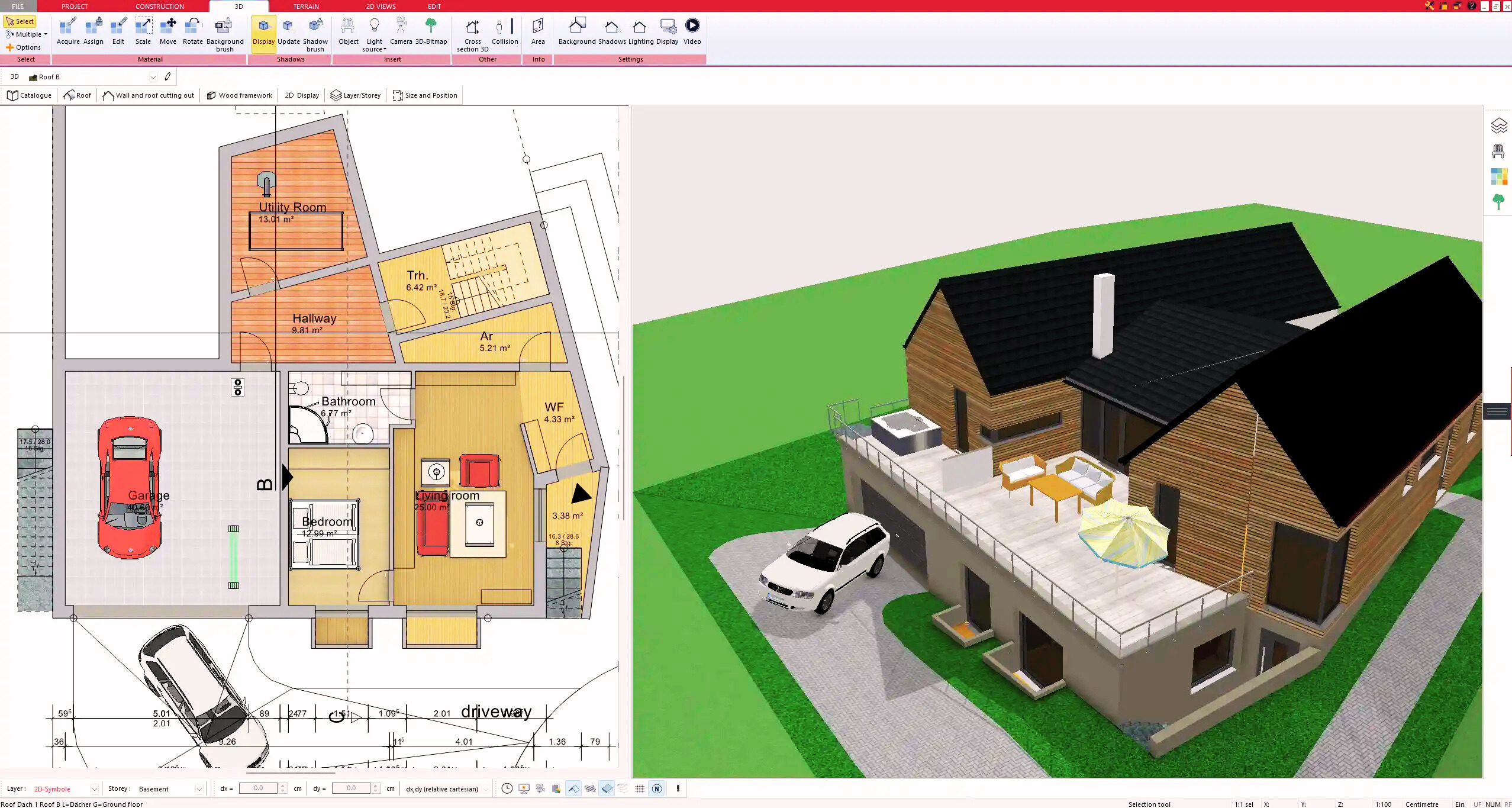
With Plan7Architect you can create professional floor plans and include the necessary details for HVAC, plumbing, and electrical layouts directly in your project. The software allows you to switch between European and American measurement units, making it easy to plan accurately no matter where your project is located. You can visualize your entire building in 3D, check the placement of ducts, pipes, and wiring, and prepare detailed plans for both residential and commercial projects. As a customer, you benefit from a 14-day cancellation policy that replaces a trial version, so you can purchase without risk and simply cancel by email if needed. This makes Plan7Architect the ideal tool if you want full control over your construction planning.
Plan your project with Plan7Architect
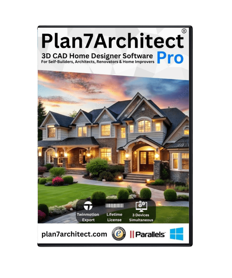
Plan7Architect Pro 5 for $99.99
You don’t need any prior experience because the software has been specifically designed for beginners. The planning process is carried out in 5 simple steps:
1. Draw Walls
2. Windows & Doors
3. Floors & Roof
4. Textures & 3D Objects
5. Plan for the Building Permit
6. Export the Floor Plan as a 3D Model for Twinmotion

- – Compliant with international construction standards
- – Usable on 3 PCs simultaneously
- – Option for consultation with an architect
- – Comprehensive user manual
- – Regular updates
- – Video tutorials
- – Millions of 3D objects available
Why Thousands of Builders Prefer Plan7Architect
Why choose Plan7Architect over other home design tools?