To read construction drawings, always begin with the basics:
-
Look at the title block to see the project name, scale, date, and author.
-
Identify the scale and units used in the drawing.
-
Recognize the drawing type: floor plan, elevation, section, or detail.
-
Learn the symbols, line types, and abbreviations that explain materials, fixtures, and dimensions.
Once you understand these points, you can read almost any construction drawing confidently.
What Construction Drawings Contain
Title Block and Project Information
The title block is your orientation point. It usually contains:
-
Project name and address
-
Architect or designer’s name
-
Date of issue and drawing number
-
Scale used (metric such as 1:100 or imperial such as 1/4” = 1’-0”)
-
Revisions or updates
Without checking the title block, it is easy to misread the entire drawing.
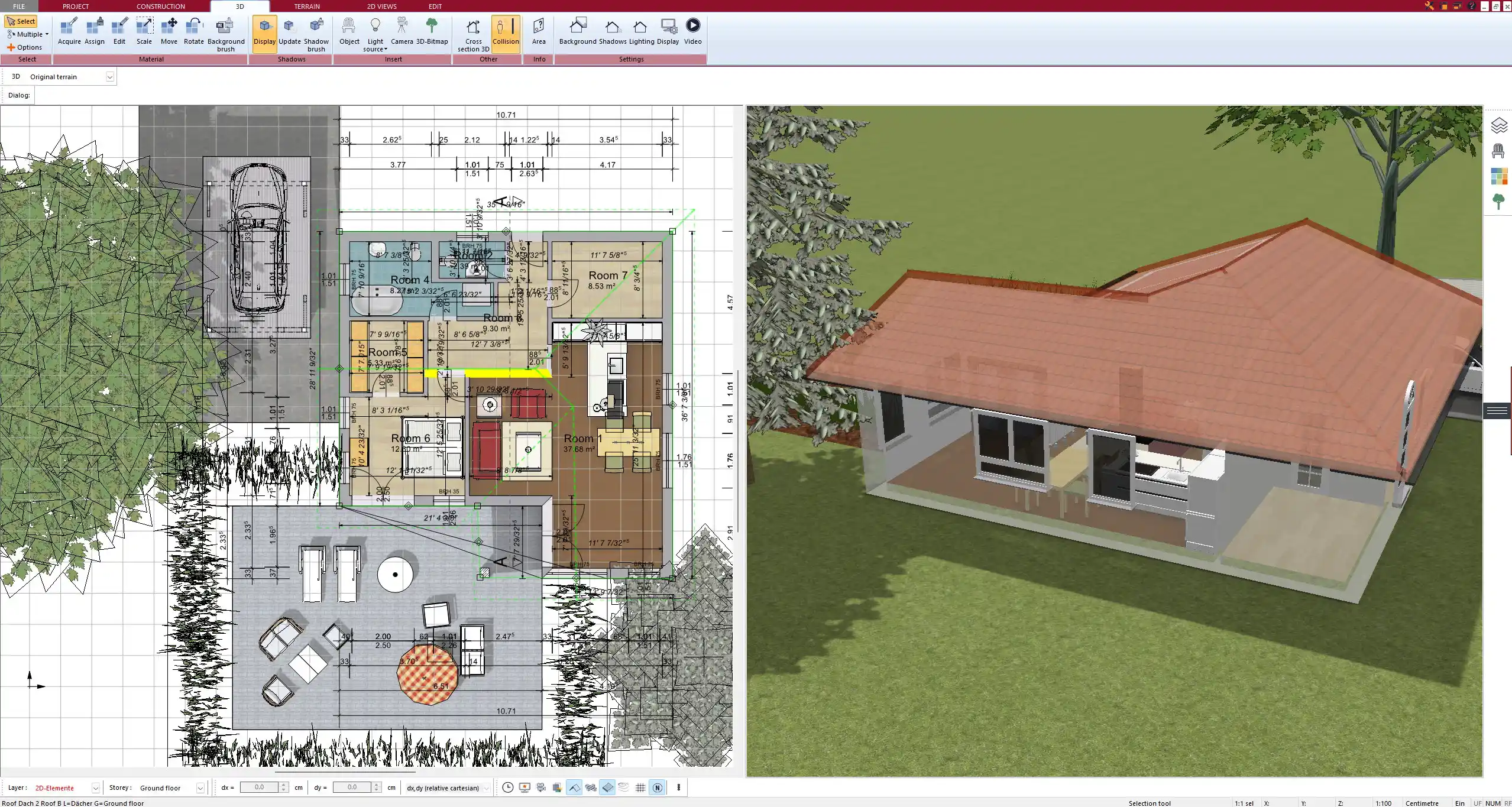
Floor Plans
A floor plan shows the building as if you were looking from above. You will see:
-
Walls, doors, and windows
-
Room names and dimensions
-
Staircases and circulation areas
-
Key fixtures such as sinks, toilets, and kitchen layouts
The floor plan gives you the clearest overview of the building’s layout.
Elevations
Elevations are exterior views of the building from different sides. They provide:
-
Wall finishes and façade materials
-
Roof slopes and height levels
-
Position of doors, windows, and balconies
Elevations help you understand how the building looks from the outside.
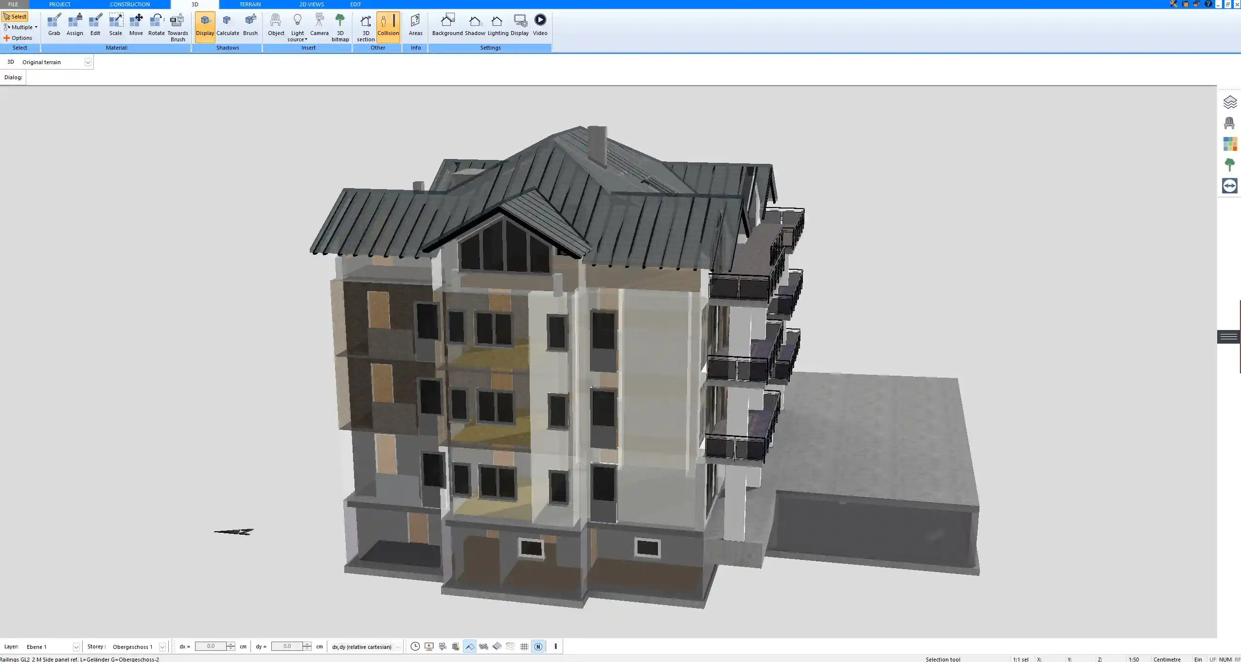
Sections and Details
Sections cut through the building vertically to show the internal structure. They include:
-
Foundation depths
-
Floor levels and ceiling heights
-
Roof structures and insulation layers
Details are enlarged parts of the drawing, often showing how windows are installed, how materials meet, or how structural elements are connected.
Key Symbols and Notations to Know
Construction drawings use a visual language of lines and symbols. Common ones include:
-
Lines: solid lines for visible edges, dashed lines for hidden elements, thick lines for walls, thin lines for dimensions.
-
Symbols: icons for electrical outlets, plumbing fixtures, light switches, and HVAC vents.
-
Tags: labels for windows and doors, often referring to a schedule with further details.
-
Abbreviations: material notes such as CONC for concrete, WD for wood, GYP for gypsum board.
-
Reference marks: circles or bubbles indicating where to find more information on another sheet.
A drawing legend often explains the meaning of each symbol.
Scales and Measurements
Every construction drawing is scaled down to fit on paper. Examples include:
-
Metric scales such as 1:50 or 1:100
-
Imperial scales such as 1/4” = 1’-0” or 1/8” = 1’-0”
When you measure with a scale ruler, you must use the same system as the drawing. A small difference can lead to serious errors. In Plan7Architect, you can switch between metric and imperial units depending on your region or preference.
Common Types of Construction Drawings
Construction projects require multiple drawing types, each with a different purpose:
| Drawing Type | Purpose |
|---|---|
| Architectural | Layouts, design, appearance |
| Structural | Beams, columns, foundations |
| Mechanical/Electrical/Plumbing (MEP) | Systems for comfort and utilities |
| Site Plan | Plot boundaries, landscaping, access |
| Detail Sheets | Enlarged construction methods |
Each set of drawings must be read together for a complete understanding.
Tips for Beginners
-
Always start with the legend and title block.
-
Read the general layout before diving into details.
-
Cross-check between floor plans, elevations, and sections.
-
Pay attention to notes and revisions—they often include crucial updates.
-
Keep a scale ruler handy when working with printed drawings.
Tip: If you ever feel lost, focus first on walls, doors, and windows. Once you recognize the basic structure, the rest becomes easier to interpret.
Practical Example – Reading a Floor Plan Step by Step
-
Begin with the title block: check project name, scale, and date.
-
Look at the scale: for example, 1:100 (metric) or 1/4” = 1’-0” (imperial).
-
Trace the walls, doors, and windows to understand the layout.
-
Check dimensions to see exact room sizes.
-
Look for notes and symbols such as stairs, electrical outlets, or plumbing fixtures.
-
Compare with the elevations and sections to visualize the full building.
Why Reading Drawings Matters
Being able to read construction drawings ensures:
-
Fewer mistakes on-site
-
Better communication between all parties
-
More accurate cost and material planning
-
Greater confidence in the building process
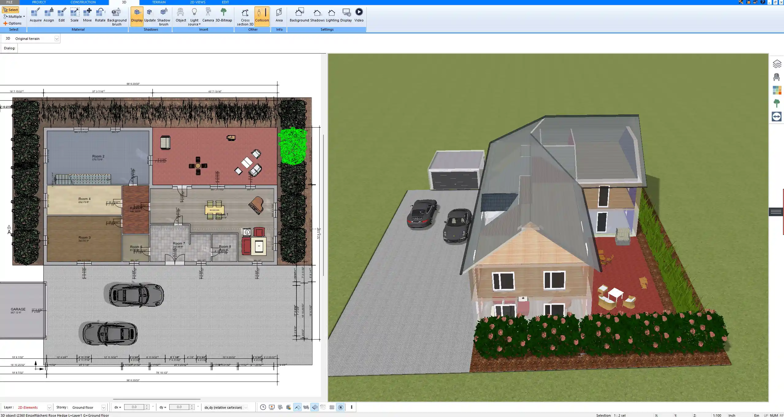
Create Professional Floor Plans with Plan7Architect
With Plan7Architect, you can design and read professional construction drawings yourself. The software allows you to create detailed floor plans, elevations, and sections just like in professional blueprints. You can easily switch between European and American units, making it suitable no matter where you build. If you want to plan your own project with precision, Plan7Architect gives you all the tools you need in one program. Customers benefit from a 14-day right of withdrawal, so you can cancel your purchase simply by email if you change your mind. This makes it the perfect alternative to a trial version.
Plan your project with Plan7Architect

Plan7Architect Pro 5 for $109.99
You don’t need any prior experience because the software has been specifically designed for beginners. The planning process is carried out in 5 simple steps:
1. Draw Walls

2. Windows & Doors

3. Floors & Roof

4. Textures & 3D Objects

5. Plan for the Building Permit

6. Export the Floor Plan as a 3D Model for Twinmotion

- – Compliant with international construction standards
- – Usable on 3 PCs simultaneously
- – Option for consultation with an architect
- – Comprehensive user manual
- – Regular updates
- – Video tutorials
- – Millions of 3D objects available
Why Thousands of Builders Prefer Plan7Architect
Why choose Plan7Architect over other home design tools?